Ford Mustang (1999-2004) Service Manual: Anti-Theft - Passive Anti-Theft System (PATS) (Diagnosis and Testing)
Refer to Wiring Diagrams Cell 112 , Anti-Theft for schematic and connector information.
Refer to Wiring Diagrams Cell 60 , Instrument Cluster for schematic and connector information.
Special Tool(s)
 |
73III Automotive Meter 105-R0057 or equivalent |
 |
Worldwide Diagnostic System (WDS) 418-F224, New Generation STAR (NGS) Tester 418-F052, or equivalent diagnostic tool |
Inspection and Verification
NOTE: PATS must be reconfigured upon installment of a new instrument cluster.
1. Verify the customer concern by duplicating the condition.
2. Visually inspect for obvious signs of mechanical and electrical damage.
Visual Inspection Chart
| Mechanical | Electrical |
|
|
3. If the concern remains after the inspection, connect the diagnostic tool to the data link connector (DLC) located beneath the instrument panel and select the vehicle to be tested from the diagnostic tool menu. If the diagnostic tool does not communicate with the vehicle:
- check that the program card is correctly installed.
- check the connections to the vehicle.
- check the ignition switch position.
4. If the diagnostic tool still does not communicate with the vehicle, refer to the diagnostic tool manual.
5. Carry out the DATA LINK DIAGNOSTIC TEST. If diagnostic tool responds with:
- CKT914, CKT915 or CKT70 = ALL ECUS NO RESP/NOT EQUIP, refer to Section .
- NO RESP/NOT EQUIP for instrument cluster, go to Pinpoint Test A.
- SYSTEM PASSED, retrieve and record the continuous diagnostic trouble codes (DTCs), erase the continuous DTCs and carry out self-test diagnostics for the instrument cluster.
6. If the DTCs retrieved are related to the concern, go to Instrument Cluster Diagnostic Trouble Code (DTC) Index to continue diagnostics.
7. If no DTCs related to the concern are retrieved, proceed to Symptom Chart to continue diagnostics.
Instrument Cluster Diagnostic Trouble Code (DTC) Index
| DTC | Description | Source |
| B1202 | Fuel Sender Open Circuit | ICM |
| B1204 | Fuel Sender Short to Ground | ICM |
| B1213 | Anti-Theft Number of Programmed Keys is Below Minimum | ICM |
| B2103 or B1232 | Antenna Not Connected - Defective Transceiver | ICM |
| B1317 | Battery Voltage High | ICM |
| B1318 | Battery Voltage Low | ICM |
| B1342 | ECU Is Defective | ICM |
| B1356 | Ignition Run Circuit Open | ICM |
| B1364 | Ignition Start Circuit Open | ICM |
| B1600 | PATS Ignition Key Transponder Signal Is Not Received - Damaged Key or Non-PATS Key | ICM |
| B1601 | PATS Received Incorrect Key-Code From Ignition Key Transponder (Unprogrammed Encoded Ignition Key) | ICM |
| B1602 | PATS Received Invalid Format Of Key-Code From Ignition Key Transponder (Partial Key Read) | ICM |
| B1681 | PATS Transceiver Signal Is Not Received (Not Connected, Damaged, or Wiring) | ICM |
| B2139 | PCM ID Does Not Match Between Instrument Cluster and PCM | ICM |
| B2141 | NVM Configuration Failure (No PCM ID Exchange Between Instrument Cluster and PCM) | ICM |
| B2143 | NVM Memory Failure | ICM |
| C1284 | Oil Pressure Switch Failure | ICM |
| U1147 | SCP Invalid or Missing Data for Vehicle Security | PCM/SCP |
| U1262 | Missing SCP Message | J1850 |
Symptom Chart
| Condition | Possible Sources | Action |
|
|
|
|
|
|
|
|
|
|
|
|
Pinpoint Tests
PINPOINT TEST A: NO COMMUNICATION WITH THE INSTRUMENT CLUSTER
| Test Step | Result / Action to Take |
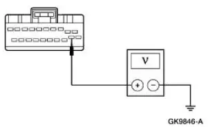
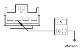
| A1 CHECK THE BATTERY POWER SUPPLY TO THE INSTRUMENT CLUSTER | Yes GO to A2 . No REPAIR the circuit. REPEAT the self-test. CLEAR the DTCs. |
|
|
| A2 CHECK THE RUN POWER SUPPLY TO THE INSTRUMENT CLUSTER | Yes GO to A3 . No REPAIR the circuit. REPEAT the self-test. CLEAR the DTCs. |
|
|
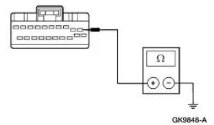
| A3 CHECK RUN/START POWER SUPPLY TO THE INSTRUMENT CLUSTER | Yes GO to A4 . No REPAIR Circuit 20 (WH/LB). REPEAT the self-test. CLEAR the DTCs. |
|
|
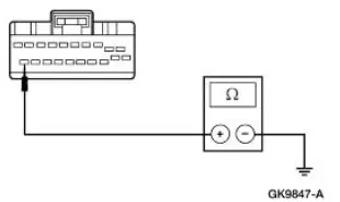
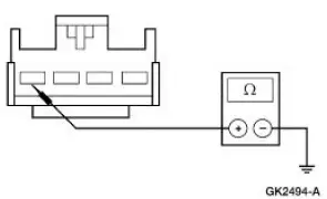
| A4 CHECK GROUND CIRCUIT 397 (BK/WH) FOR AN OPEN | Yes GO to A5 . No REPAIR the circuit. REPEAT the self-test. CLEAR the DTCs. |
|
|
| A5 CHECK GROUND CIRCUIT 1205 (BK) FOR OPEN | Yes REFER to Section. No REPAIR the circuit. REPEAT the self-test. CLEAR the DTCs. |
|
PINPOINT TEST B: THE ANTI-THEFT INDICATOR IS ALWAYS/NEVER ON - NO THREE SECOND THEFT INDICATOR PROVE OUT
| Test Step | Result / Action to Take |
| B1 ENTER THE INSTRUMENT CLUSTER ACTIVE COMMAND MODE | Yes GO to B2 . No Go To Pinpoint Test A . |
|
|
| B2 TRIGGER THE ANTI-THEFT INDICATOR | Yes The anti-theft indicator is OK. VERIFY the concern with the customer. No GO to B3 |
|
|
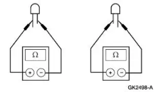
| B3 CHECK THE ANTI-THEFT INDICATOR | Yes INSTALL a new instrument cluster; for additional information, REFER to Section. CYCLE the ignition to RUN using two encoded ignition keys. Go To Pinpoint Test J to initialize the module. REPEAT the self-test. CLEAR the DTCs. No INSTALL a new anti-theft LED. For additional information, REFER to Section. REPEAT the selftest. CLEAR the DTCs. |
|
PINPOINT TEST C: THE ANTI-THEFT SYSTEM DOES NOT OPERATE CORRECTLY - THE VEHICLE STARTS BUT FLASHES A FAULT CODE ON THE THEFT INDICATOR AT KEY ON
| Test Step | Result / Action to Take |
| C1 CHECK THE ANTITHEFT INDICATOR FOR CORRECT OPERATION | Yes If the vehicle starts, VERIFY correct PCM calibration for vehicle. REFER to Powertrain Control/Emissions Diagnosis (PC/ED) manual Section 3. No GO to C2 . |
|
|
| C2 CHECK THE PCM DIAGNOSTIC CAPABILITY | Yes GO to C3 . No REFER to Section. |
|
|
| C3 RETRIEVE THE PCM DTCS | Yes GO to C4 . No VERIFY PCM power and ground. REFER to Powertrain Control/Emissions Diagnosis (PC/ED) manual Section 3. |
|
|
| C4 CHECK THE COMMUNICATION NETWORK | Yes INSTALL a new instrument cluster; for additional information, REFER to Section. CYCLE the ignition to RUN using two encoded ignition keys. Go To Pinpoint Test J to initialize the module. REPEAT the self-test. CLEAR the DTCs. If DTC U1147 is still present, INSTALL a new PCM; for additional information, REFER to Section. TEST the system for normal operation. (You must follow Pinpoint Test J to initialize module.) No System is OK. |
|
PINPOINT TEST D: THE ANTI-THEFT SYSTEM DOES NOT OPERATE CORRECTLY - ANTI-THEFT NUMBER OF PROGRAMMED KEYS IS BELOW MINIMUM
| Test Step | Result / Action to Take |
| D1 USE THE DTCS FROM THE INSTRUMENT CLUSTER SELF-TESTS | Yes GO to D2 . No REPAIR the other DTCs retrieved. REPEAT the Instrument Cluster On-Demand Self-Test. CLEAR the DTCs. |
|
|
| D2 CHECK FOR PROGRAMMED ENCODED IGNITION KEYS - MONITOR THE INSTRUMENT CLUSTER PID NUMKEYS | Yes GO to D3 . No System is OK. |
|
|
| D3 PROGRAM ENCODED IGNITION KEYS | Yes CLEAR the DTCs. CARRY OUT the Instrument Cluster On-Demand Self-Test to verify all codes have been cleared. REPEAT the self-test. CLEAR the DTCs. No If the theft indicator is on continuously, REPEAT TEST STEP D3 with a second new encoded ignition key. If the theft indicator is flashing, RETRIEVE DTCs stored for the new fault and REPAIR the other DTC(s) retrieved. |
|
PINPOINT TEST E: THE ANTI-THEFT SYSTEM DOES NOT OPERATE CORRECTLY - ANTENNA NOT CONNECTED OR DEFECTIVE TRANSCEIVER
| Test Step | Result / Action to Take |
| E1 INSPECT THE PATS TRANSCEIVER FOR CORRECT INSTALLATION | Yes INSTALL a new PATS transceiver module; for additional information, REFER to Module-Passive Anti-Theft Transceiver . REPEAT the Instrument Cluster On-Demand Self-Test. CLEAR the DTCs. No System is OK. |
|
PINPOINT TEST F: THE ANTI-THEFT SYSTEM DOES NOT OPERATE CORRECTLY - PATS IGNITION KEY TRANSPONDER SIGNAL IS NOT RECEIVED (DAMAGED KEY OR NON-PATS KEY)
| Test Step | Result / Action to Take |
| NOTE: Large metallic objects, electronic debit transponder devices or a second key on the same key ring as the PATS ignition key may cause vehicle starting problems and record DTCs under certain conditions. If a fault cannot be identified, examine the customer's key for such objects or devices. If present, inform the customer that they need to keep these objects from touching the PATS ignition key while starting the engine. These objects and devices cannot damage the PATS ignition key, but can cause a momentary problem if they are too close to the key during engine start. If a problem occurs, turn ignition OFF and restart the engine with all other objects on the key ring held away from the ignition key. Check to ensure the encoded ignition key used by the customer is an approved Ford encoded ignition key (encoded ignition keys from Rotunda, Ilco, Curtis, or Strattec are approved Ford encoded ignition keys). | |
| F1 USE THE DTCS FROM THE INSTRUMENT CLUSTER SELF-TESTS | Yes GO to F2 . No If other DTCs are retrieved, REFER to Instrument Cluster Diagnostic Trouble Code (DTC) Index. If no DTCs are retrieved, system is OK. |
|
|
| F2 PROGRAM A NEW ENCODED IGNITION KEY | Yes GO to F3 . No If no other DTCs are retrieved, system is OK. If other DTCs are retrieved, REFER to Instrument Cluster Diagnostic Trouble Code (DTC) Index. |
|
|
| F3 INSTALL A NEW PATS TRANSCEIVER | Yes INSTALL a new instrument cluster; for additional information, REFER to Section. CYCLE the ignition to RUN using two encoded ignition keys. Go To Pinpoint Test J to initialize the module. REPEAT the self-test. CLEAR the DTCs. No System is OK. |
|
|
PINPOINT TEST G: THE ANTI-THEFT SYSTEM DOES NOT OPERATE CORRECTLY - PATS RECEIVED INCORRECT KEY-CODE FROM IGNITION KEY TRANSPONDER (UNPROGRAMMED ENCODED IGNITION KEY)
| Test Step | Result / Action to Take |
| NOTE: Large metallic objects, electronic debit transponder devices or a second key on the same key ring as the PATS ignition key may cause vehicle starting problems and record DTCs under certain conditions. If a fault cannot be identified, examine the customer's key for such objects or devices. If present, inform the customer that they need to keep these objects from touching the PATS ignition key while starting the engine. These objects and devices cannot damage the PATS ignition key, but can cause a momentary problem if they are too close to the key during engine start. If a problem occurs, turn ignition OFF and restart the engine with all other objects on the key ring held away from the ignition key. Check to ensure the encoded ignition key used by the customer is an approved Ford encoded ignition key (encoded ignition keys from Rotunda, Ilco, Curtis, or Strattec are approved Ford encoded ignition keys) | |
| G1 USE THE DTCS FROM THE INSTRUMENT CLUSTER SELF TESTS | Yes GO to G2 . No System is OK. CHECK all customer encoded ignition keys with Instrument Cluster On-Demand Self-Test to verify all other encoded ignition keys are programmed. |
|
|
| G2 CHECK FOR PROGRAMMED ENCODED IGNITION KEYS - MONITOR THE INSTRUMENT CLUSTER PID NUMKEYS | Yes ERASE and REPROGRAM the key codes; for additional information, REFER to Key Programming- Erase All Key Codes and Program Two Keys . REPEAT the self-test. CLEAR the DTCs. No GO to G3 . |
|
|
| G3 CHECK THE NUMBER OF PROGRAMMED ENCODED IGNITION KEYS AVAILABLE | Yes GO to G4 . No CUT a new encoded ignition keys so that at least two encoded ignition keys are available. PROGRAM the encoded ignition keys; Key Programming-Erase All Key Codes and Program Two Keys . GO to G4 . |
|
|
| G4 VERIFY THE INSTRUMENT CLUSTER PID SPARE_KY INDICATES ENABLE | Yes REFER to Key Programming-Erase All Key Codes and Program Two Keys . CLEAR the DTCs, REPEAT the self-testGO to G5 . No REFER to Key Programming-Enable/Disable Spare Key Programming to enable the PID SPARE KEY to ENABLE. TEST the system for normal operation. Once completed, GO to G5 . |
|
|
| G5 CHECK THE ENCODED IGNITION KEYS FOR CORRECT OPERATION | Yes System is OK. If there are additional keys that need to be programmed, for additional information, REFER to Key Programming-Program a Key Using Two Programmed Keys . No GO to G6 . |
|
|
| G6 RETRIEVE THE INSTRUMENT CLUSTER DTCS - CHECK FOR DTC B1601 | Yes INSTALL a new instrument cluster; for additional information, REFER to Section. CYCLE the ignition to RUN using two encoded ignition keys. GO to Pinpoint Test J to initialize the vehicle. REPEAT the self-test. CLEAR the DTCs. No System is OK. If other DTCs are retrieved, REFER to Instrument Cluster Module Diagnostic Trouble Code (DTC) Index. |
|
|
PINPOINT TEST H: THE ANTI-THEFT SYSTEM DOES NOT OPERATE CORRECTLY - PATS RECEIVED INVALID FORMAT OF KEY-CODE FROM IGNITION KEY TRANSPONDER (PARTIAL KEY READ)
| Test Step | Result / Action to Take |
| NOTE: Large metallic objects, electronic debit transponder devices or a second key on the same key ring as the PATS ignition key may cause vehicle starting problems and record DTCs under certain conditions. If a fault cannot be identified, examine the customer's key for such objects or devices. If present, inform the customer that they need to keep these objects from touching the PATS ignition key while starting the engine. These objects and devices cannot damage the PATS ignition key, but can cause a momentary problem if they are too close to the key during engine start. If a problem occurs, turn ignition OFF and restart the engine with all other objects on the key ring held away from the ignition key. Check to ensure the encoded ignition key used by the customer is an approved Ford encoded ignition key (encoded ignition keys from Rotunda, Ilco, Curtis, or Strattec are approved Ford encoded ignition keys). | |
| H1 USE THE DTCS FROM THE INSTRUMENT CLUSTER SELF TESTS | Yes GO to H2 . No System is OK. CHECK all customer encoded ignition keys with Instrument Cluster On-Demand Self-Test to verify all other keys are programmed. |
|
|
| H2 OBTAIN A NEW ENCODED IGNITION KEY | Yes GO to H3 . No System is OK. If the customer has any remaining encoded keys at home, instruct them to carry out Key Programming-Program a Key Using Two Programmed Keys on each remaining key. This procedure is detailed in the Owners Guide. |
|
|
| H3 INSTALL A NEW PATS TRANSCEIVER | Yes REFER to Instrument Cluster Diagnostic Trouble Code (DTC) Index. No System is OK. |
|
|
PINPOINT TEST I: THE ANTI-THEFT SYSTEM DOES NOT OPERATE CORRECTLY - PATS TRANSCEIVER SIGNAL IS NOT RECEIVED (NOT CONNECTED, DAMAGED, OR WIRING)
| Test Step | Result / Action to Take |
| I1 USE THE DTCS FROM THE INSTRUMENT CLUSTER SELF TESTS | Yes GO to I2 . No System is OK. |
|
|
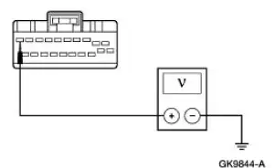
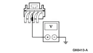
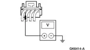
| I2 CHECK THE PATS TRANSCEIVER FOR VOLTAGE - CIRCUIT 20 (WH/LB) | Yes GO to I3 . No REPAIR Circuit 20 (WH/LB). REPEAT the self-test. CLEAR the DTCs. |
|
|
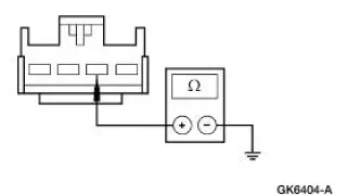
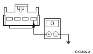
| I3 CHECK THE PATS TRANSCEIVER GROUND - CIRCUIT 397 (BK/WH) | Yes GO to I4 . No REPAIR Circuit 397 (BK/WH). REPEAT the self-test. CLEAR the DTCs. |
|
|
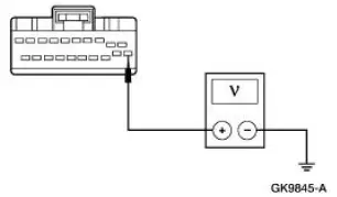
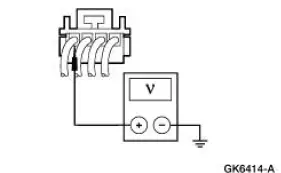
| I4 CHECK THE PATS TRANSCEIVER RECEIVE CIRCUIT FOR VOLTAGE - CIRCUIT 1216 (GY/OG) | Yes GO to I6 . No GO to I5 . |
|
|
| I5 CHECK THE PATS TRANSCEIVER RECEIVE CIRCUIT FOR SHORT TO GROUND - CIRCUIT 1216 (GY/OG) | Yes GO to I6 . No CHECK Circuit 1216 (GY/OG) for short to ground. If the circuit is OK, INSTALL a new instrument cluster; for additional information, REFER to Section. CYCLE the ignition key to RUN using two encoded ignition keys. GO to Pinpoint Test J to initialize the module. REPEAT the selftest. CLEAR the DTCs. If the circuit is not OK, REPAIR Circuit 1216 (GY/OG). CLEAR the DTCs. TEST the system for normal operation. |
|
|
| I6 CHECK CIRCUIT 1216 (GY/OG) FOR OPEN | Yes GO to I7 . No REPAIR Circuit 1216 (GY/OG). CLEAR the DTCs. TEST the system for normal operation |
|
|
| I7 CHECK THE PATS TRANSCEIVER TRANSMIT CIRCUIT FOR VOLTAGE - CIRCUIT 1215 (WH/LG) | Yes GO to I9 . No GO to I8 . |
|
|
| I8 CHECK THE PATS TRANSCEIVER TRANSMIT CIRCUIT FOR OPEN - CIRCUIT 1215 (WH/LG) | Yes GO to I9 . No CHECK Circuit 1215 (WH/LG) for short to ground. If the circuit is OK, INSTALL a new instrument cluster; for additional information, REFER to Section. CYCLE the ignition to RUN using two encoded ignition keys. GO to Pinpoint Test J to initialize the module. REPEAT the self-test. CLEAR the DTCs. If the circuit is not OK, REPAIR Circuit 1215 (WH/LG). REPEAT the self-test. CLEAR the DTCs |
|
|
| I9 CHECK THE PATS TRANSMIT CIRCUIT FOR CORRECT OPERATION - CIRCUIT 1215 (WH/LG) | Yes GO to I10 . No CHECK Circuit 1215 (WH/LG) for continuity to instrument cluster C220aPin 8. If the circuit is OK, INSTALL a new instrument cluster; for additional information, REFER to Section. CYCLE the ignition to RUN using two encoded ignition keys. GO to Pinpoint Test J to initialize the module. REPEAT the self-test. CLEAR the DTCs. If the circuit is not OK, REPAIR Circuit 1215 (WH/LG). REPEAT the self-test. CLEAR the DTCs. |
|
|
| I10 CHECK THE PATS SYSTEM WITH A NEW PATS TRANSCEIVER INSTALLED | Yes GO to I11 . No System is OK. |
|
|
| I11 CHECK THE PATS SYSTEM WITH NEW INSTRUMENT CLUSTER | Yes REPAIR Circuit 397 (BK/WH), 20 (WH/LB), 1215 (WH/LG), and 1216 (GY/OG). REPEAT the selftest. CLEAR the DTCs. No If no DTCs are retrieved, the system is OK. If other DTCs are retrieved, REFER to Instrument Cluster Diagnostic Trouble Code (DTC) Index. |
|
PINPOINT TEST J: THE ANTI-THEFT SYSTEM DOES NOT OPERATE CORRECTLY - PCM ID DOES NOT MATCH BETWEEN INSTRUMENT CLUSTER AND PCM
| Test Step | Result / Action to Take |
| J1 USE THE DTCS FROM THE INSTRUMENT CLUSTER SELF TESTS | Yes GO to J2 . No System is OK. |
|
|
| J2 CLEAR PCM ID FROM INSTRUMENT CLUSTER AND PCM | Yes VERIFY PCM calibration is correct for the vehicle. If correct, REPEAT Step J2. If fault code persists, INSTALL a new instrument cluster; for additional information, REFER to Section. CYCLE the ignition to RUN using two encoded ignition keys. REPEAT Pinpoint Test J . CLEAR the DTCs. TEST the system for normal operation. If DTC B2139 still exists, INSTALL a new PCM; for additional information, REFER to Section. REPEAT the self-test. CLEAR the DTCs. No System is OK. CHECK for any other DTCs. REFER to the instrument cluster Diagnostic Trouble Code Index. |
|
PINPOINT TEST K: THE ANTI-THEFT SYSTEM DOES NOT OPERATE CORRECTLY - NVM CONFIGURATION FAILURE (NO PCM ID EXCHANGED BETWEEN INSTRUMENT CLUSTER AND PCM)
| Test Step | Result / Action to Take |
| K1 USE THE DTCS FROM THE INSTRUMENT CLUSTER SELF TESTS | Yes If DTC B2141 only is retrieved, GO to K2 . If DTC U1147 is retrieved with DTC B2141, GO to Pinpoint Test C . No System is OK. |
|
|
| K2 CARRY OUT KEEP ALIVE MEMORY RESET FROM PCM | Yes System is OK. No GO to K3 . |
|
|
| K3 RETRIEVE THE INSTRUMENT CLUSTER DTCS | Yes REPEAT K2. If the fault persists, verify the PCM calibration. If the calibration is OK, INSTALL a new instrument cluster. for additional information, REFER to Section. Cycle the ignition key to run using two encoded ignition keys. GO to Pinpoint Test J to initialize the module. REPEAT the self-test. CLEAR the DTCs. No REFER to the DTC index. |
|
 Anti-Theft - Passive Anti-Theft System (PATS) (Description and Operation)
The passive anti-theft system (PATS) contains the following components:
theft indicator
encoded ignition key
transceiver module
instrument cluster
powertrain control module (PCM)
standard corpo ...
 Key Programming - Erase All Key Codes and Program Two
Keys
Key Programming - Erase All Key Codes and Program Two
Keys
Special Tool(s)
Worldwide Diagnostic System
(WDS)
418-F224,
New Generation STAR (NGS)
Tester
418-F052 or equivalent
diagnostic tool
NOTE: This procedure is used when a custom ...
Other materials:
Driver and passenger airbags
WARNING: Never place your arm or any objects over an airbag
module. Placing your arm over a deploying airbag can result in
serious arm fractures or other injuries. Objects placed on or over the
airbag inflation area may cause those objects to be propelled by t ...
Sensor Indicator - Rear
Special Tool(s)
Pinion Bearing Cone Remover
205-D002 (D79P-4621A)
Axle Bearing/Seal Plate
205-090 (T75L-1165-B)
Sensing Ring Replacer
206-041 (T89P-20202-A)
Removal
1. Remove the rear axle shaft bearing.
2. Using the special ...
Charge Air Cooler
Material
Item
Specification
Silicone Gasket and Sealant
F7AZ-19554-EA or equivalent
WSE-M4G323-EA
Removal and Installation
1. Drain the supercharger coolant. For additional information, refer to
Section.
2. Release the fuel pressure. F ...
