Ford Mustang (1999-2004) Service Manual: Axle Assembly
Removal and Installation
1. CAUTION: The vehicle must be on level ground and at curb height.
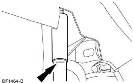
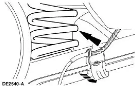
Mark the rear shock absorbers relative to their protective sleeve.
- During installation, raise the suspension to this reference mark before tightening the suspension fasteners.
2. Raise and support the vehicle.
3. Remove the rear wheel and tire assemblies.
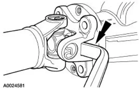
4. CAUTION: Index-mark the driveshaft flange and pinion flange (4851) to maintain initial balance during installation.
CAUTION: The driveshaft centering socket yoke fits tightly on the pinion flange pilot. Never hammer on the driveshaft or any of its components to disconnect the yoke from the flange. Pry only in the area shown, with a suitable tool, to disconnect the yoke from the flange.
Disconnect and position the driveshaft out of the way.
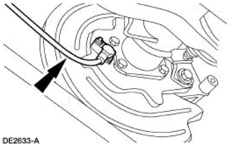
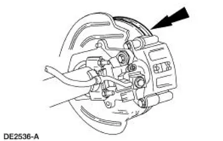
5. NOTE: If necessary, use Rust Penetrant and Inhibitor F2AZ-19A501-A meeting Ford specification ESR-M99C56-A to loosen the sensor for removal.
Remove the rear anti-lock brake sensors from the rear disc brake adapters.
6. CAUTION: Index-mark the brake discs and the wheel studs prior to brake disc removal.
CAUTION: Do not allow the calipers to hang from the brake hoses.
Remove the rear brake discs.
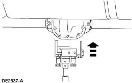
7. CAUTION: Secure the differential housing (4010) to the jack with a suitable strap.
Support the differential housing with a suitable hi-lift jack.
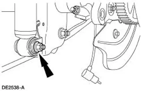
8. Remove and discard the nuts and bolts retaining the shock absorbers to the axle.
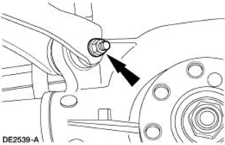
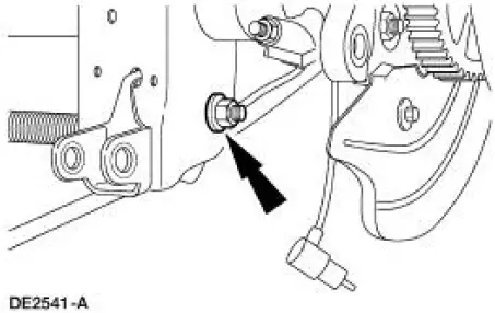
9. Remove and discard the nuts and bolts retaining the upper suspension arm and bushings to the differential housing.
10. Lower the axle slightly, and remove the springs.
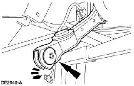
11. Remove and discard the nuts and bolts retaining the lower suspension arm and bushings to the axle.
12. Disconnect the lower suspension arm and bushings from the axle.
13. Remove the axle from the vehicle.
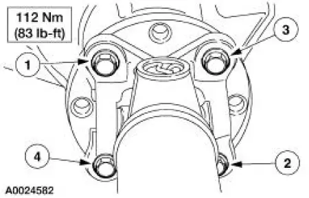
14. CAUTION: Align the index marks on the driveshaft centering socket yoke and the pinion flange.
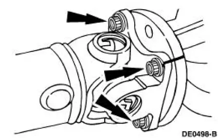
CAUTION: Install the driveshaft with new bolts. If new bolts are not available, apply Threadlock and Sealer EOAZ-19554-AA or equivalent meeting Ford specification WSKM2G351- A5 to the threads of the original bolts.
CAUTION: The driveshaft centering socket yoke fits tightly on the pinion flange pilot. To make sure that the yoke seats squarely on the flange, tighten the bolts evenly in a cross pattern as shown.
CAUTION: Raise the suspension to the reference marks on the rear shock absorbers before tightening the suspension fasteners.
NOTE: Apply High Temperature Nickel Anti-Sieze Lubricant F6AZ-9L494-AA meeting Ford specification ESE-M124A-A to the rear anti-lock brake sensor body where it will make contact when installed.
To install, reverse the removal procedure.
- Refer to Section for rear suspension fastener tightening specifications.
- Refer to Section for wheel nut tightening specification.
- Check and, if necessary, fill the axle with the specified lubricant to the specified level. For additional information, refer to Specifications in this section.
 Differential Case and Ring Gear
Special Tool(s)
2-Jaw Puller
205-D072 (D97L-4221-A) or
equivalent
Installer, Differential Side
Bearing
205-009 (T57L-4221-A1)
Step Plate
205-D016 (D80L-630-5) or
...
Other materials:
Torque Converter Cleaning And Inspection
Material
Item
Specification
MERCON V Automatic
Transmission Fluid
XT-5-QM, XT-5-DM
MERCON V
1. If a new torque converter is being installed, continue with Substep 2 of
Step 2.
2. If a new torque converter is not being installed, the fol ...
Halfshaft Joint
Special Tool(s)
Driver
205-199 (T83T-3132-A1)
Hub Bearing Cup Replacer
205-147 (T80T-4000-P)
Sensing Ring Replacer
206-041 (T89P-20202-A)
Disassembly
1. CAUTION: Do not disassemble the halfshaft assembly. Install a new
assem ...
Traction Control
PRINCIPLES OF OPERATION
The traction control system helps avoid drive wheel spin and loss of
traction.
If your vehicle begins to slide, the system applies the brakes to individual
wheels and, when needed, reduces engine power at the same time. If the
wheels s ...
