Ford Mustang (1999-2004) Service Manual: Communication Circuit Wiring Repair
Special Tool(s)
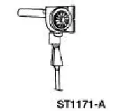 |
Heat Gun 107-R0300 or equivalent |
1. Disconnect the battery ground cable. For additional information, refer to Section.
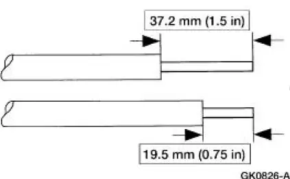
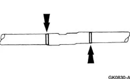
2. Strip the wires.
3. NOTE: Use rosin core mildly activated (RMA) solder, not acid core solder.
Solder the wires.
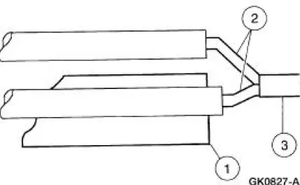
1. Install the heat shrink tube.
2. Twist the wires together.
3. Solder the wires together.
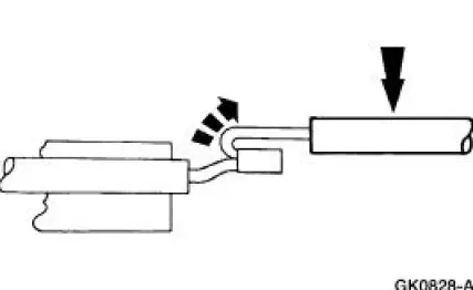
4. NOTE: Wait for the solder to cool before moving the wires.
Bend the wires back in a straight line.
5. Position the (A) heat shrink tube over the (B) wire repair.
- Overlap the heat shrink tube on both wires.
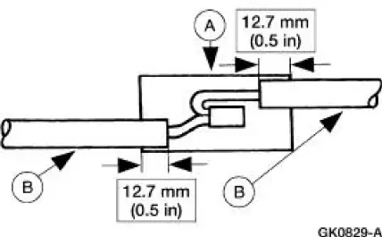
6. Use the heat gun to heat the repaired area until adhesive flows out both ends of the heat shrink tube.
7. Reconnect the battery ground cable.
 Pinpoint Tests
CAUTION: Be careful when probing the CJB, battery junction box (BJB)
or any
connectors. Damage will result to the connector receptacle if the probe or
terminal being used
is too large.
CAUTION ...
 Module Configuration
Module Configuration (Diagnosis and Testing)
Special Tool(s)
Worldwide Diagnostic System
(WDS)
418-F224
New Generation STAR (NGS)
Tester
418-F052 or equivalent
diagnostic tool ...
Other materials:
Safety Belt System (Description and Operation)
WARNING: All safety belt assemblies include retractors, buckles, front
seat belt buckle
support assemblies (slide bar, if so equipped), shoulder belt height adjuster
(if equipped), child
safety seat tether bracket assemblies (if equipped) and attaching hardw ...
Hydraulic Control Unit
Removal
1. Disconnect the battery ground cable(14301).
2. Disconnect the anti-lock-brake control module electrical connector.
3. NOTE: The 4 wheel anti-lock brake system (4WABS) with traction
control is shown , the
4WABS without traction control system is ...
Load Carrying
LOAD LIMIT
Vehicle Loading – With and Without a Trailer
Vehicle Loading – With and Without a Trailer
This section will guide you in the proper loading of your vehicle and/or
trailer, to keep your loaded vehicle weight within its design rating
capability, w ...
