Ford Mustang (1999-2004) Service Manual: General Information
INTRODUCTION
In the past, when cars were simpler, diagrams were simpler. All components were connected by wires, and diagrams seldom exceeded 4 pages in length. Today, some wiring diagrams require more than 16 pages. It would be impractical to expect a service technician to trace a wire from page 1 across every page to page 16.
Components shown with a dashed line instead of a solid line indicate not all circuits are shown in this particular diagram (circuits shown in system diagrams are typically applicable to that system only). The remaining circuits connected to that component will be shown in the appropriate system that they apply to.
Today, the wiring diagram necessary to support a given repair procedure is included within that article or a link is provided to the appropriate SYSTEM WIRING DIAGRAM article. For example, the wiring diagram for a Ford EEC-IV system may be included in ENGINE PERFORMANCE and WIRING DIAGRAMS articles for Ford Motor Co. The wiring diagram for a cruise control system may be included in ACCESSORIES & EQUIPMENT section for the specific vehicle manufacturer, and the wiring diagram for an anti-lock brake system may be included in BRAKES and WIRING DIAGRAMS for the specific manufacturer.
WIRING DIAGRAMS contains all wiring diagrams not included in STARTING & CHARGING SYSTEMS and ACCESSORIES & EQUIPMENT. This includes: Data Link Connectors, Ground Distribution, Power Distribution, Engine Performance, Electric Cooling Fans, Anti-Lock Brakes, Electronic Suspension and Electronic Steering wiring diagrams. The Data Link Connectors wiring diagrams show the circuits by which the various on-board computers exchange information, and the diagnostic connectors used for diagnosis and their location. The Ground Distribution wiring diagrams show all vehicle ground points, their location, and the components common to those ground points. The Power Distribution wiring diagrams show the power feed circuits and the components common to those power feeds.
Wiring diagrams used to support the information in ACCESSORIES & EQUIPMENT are drawn in a "topdown" format. The diagrams are drawn with the power source at the top of the diagram and the ground point at the bottom of the diagram. Component locations are identified on the wiring diagrams. Any wires that do not connect directly to a component are identified on the diagram to indicate where they go.
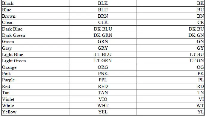
WIRING DIAGRAM COLOR ABBREVIATIONS
COLOR ABBREVIATIONS
Color Normal Optional
WIRING DIAGRAM SYMBOLS
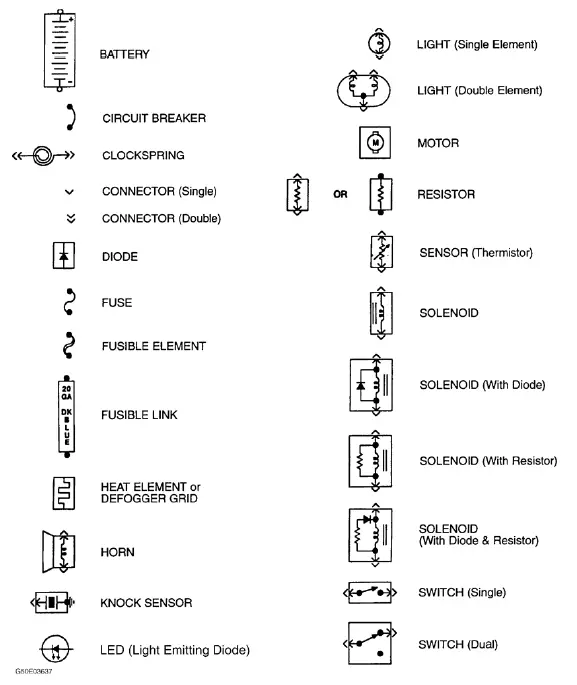
Fig. 1: Identifying Standard Wiring Diagram Symbols
WIRING DIAGRAM GROUND NUMBER LOCATIONS
NOTE: The following illustration depicts standardized ground numbers and locations to be used in conjunction with wiring diagrams applying to 2001 and prior model years only. See Fig. 2 . Wiring diagrams applying to newer model years depict manufacturer-specified ground numbers and locations. Do not utilize the illustration with 2002 and newer model year wiring diagrams.
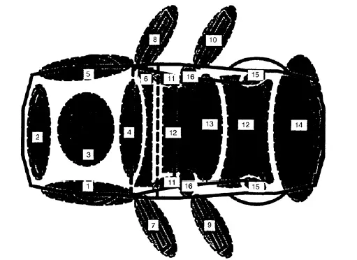
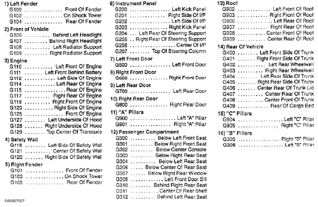
Fig. 2: Ground Numbers & Locations (2001 & Prior Model Years)
WIRING DIAGRAM COMPONENT LOCATIONS
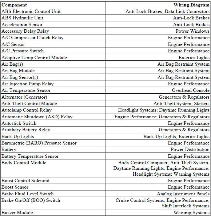
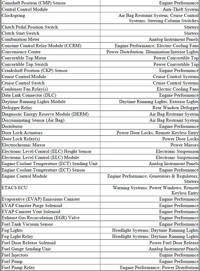
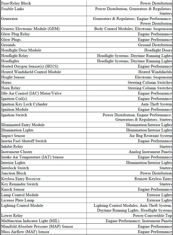
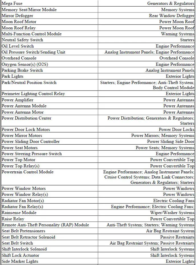
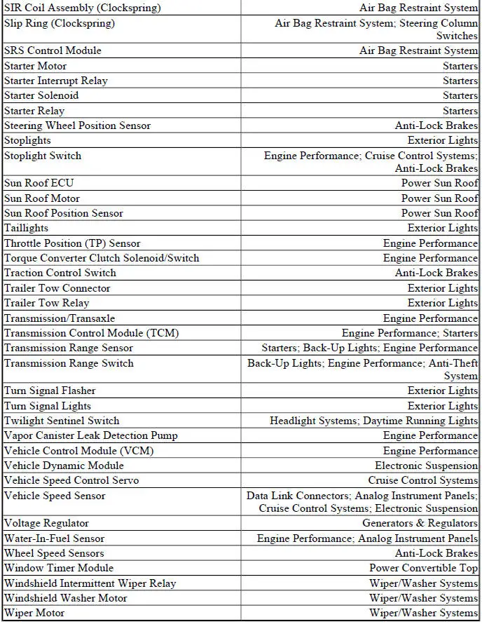
When trying to locate a component in a wiring diagram and you don't know the specific system where it is located, use this handy component locator to find the system wiring diagram in which the component is located. Then, go to that system and locate the component within the wiring diagram.
For example, if you don't know the specific system in which the ignition switch is located, look up ignition switch in the wiring diagram component location tables and go to the appropriate wiring diagram(s) which contain either full or partial views of the ignition switch. The full view of the ignition switch is located in Power Distribution.
The first listing for the component will be the full or most complete view of the component. Additional listings will be partial views of the component. Not all components are used on all models.
All components will have a partial view in Ground Distribution and Power Distribution. Data Link Connectors show connecting circuits between modules. Alternate names for components may be listed in wiring diagram component locations tables.
WIRING DIAGRAM COMPONENT LOCATIONS
SYSTEM WIRING DIAGRAMS Ford - Mustang
AIR CONDITIONING
3.8L
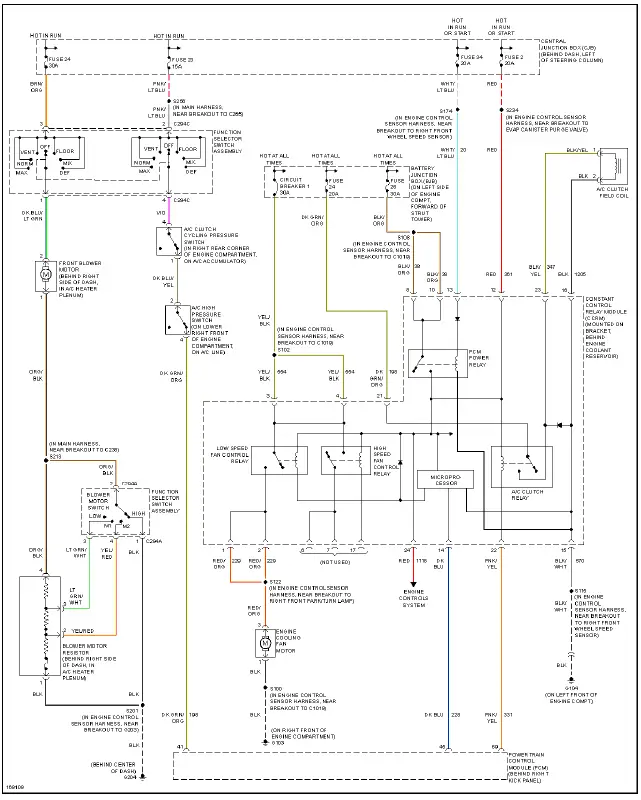
Fig. 1: 3.8L, Air Conditioning Circuit
4.6L
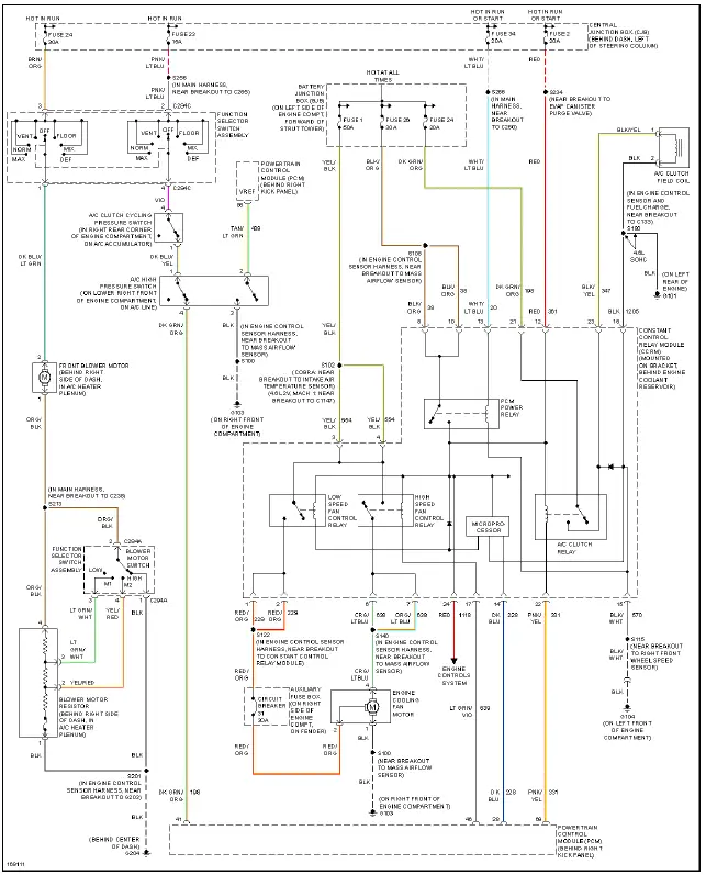
Fig. 2: 4.6L, Air Conditioning Circuit
ANTI-LOCK BRAKES
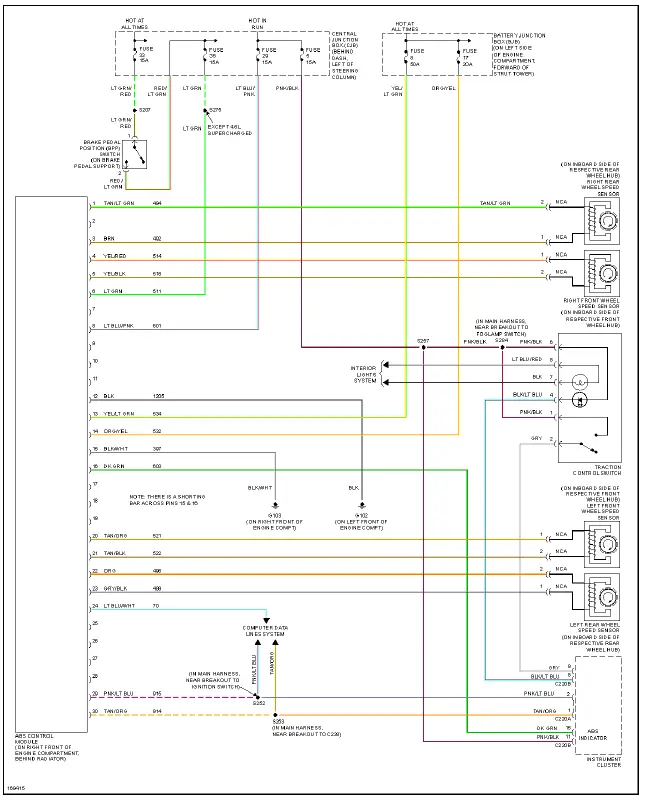
Fig. 3: Anti-lock Brakes Circuit
ANTI-THEFT
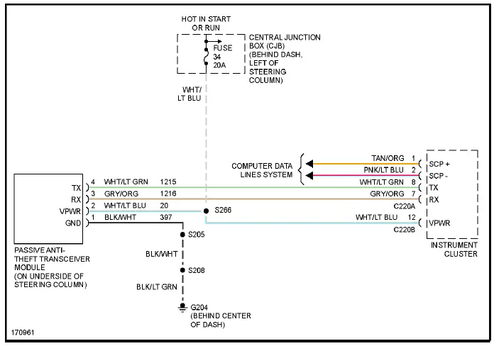
Fig. 4: Passive Anti-theft Circuit
BODY CONTROL MODULES
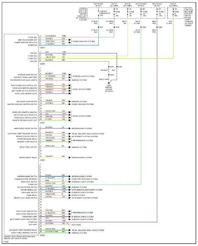
Fig. 5: Body Control Modules Circuit
COMPUTER DATA LINES
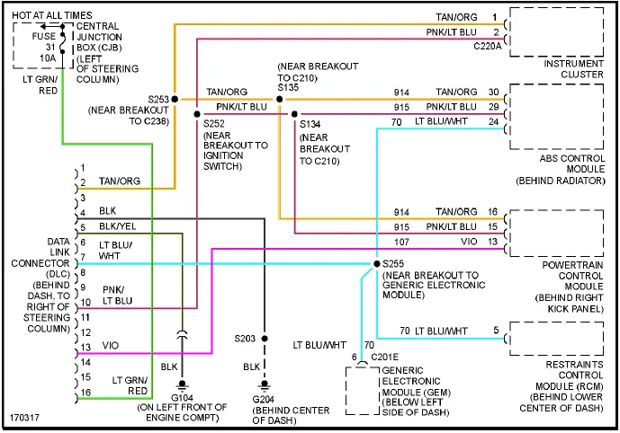
Fig. 6: Computer Data Lines Circuit
COOLING FAN
3.8L
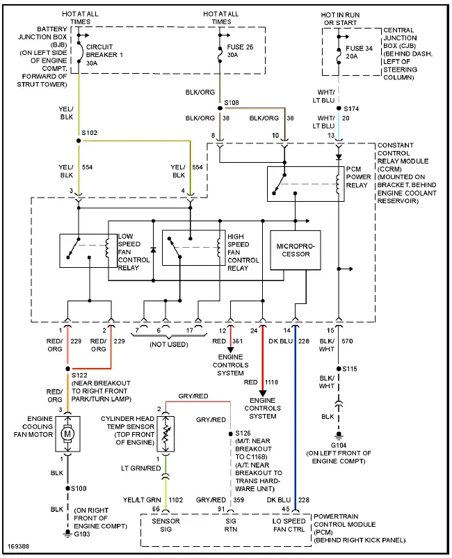
Fig. 7: 3.8L, Cooling Fan Circuit
4.6L
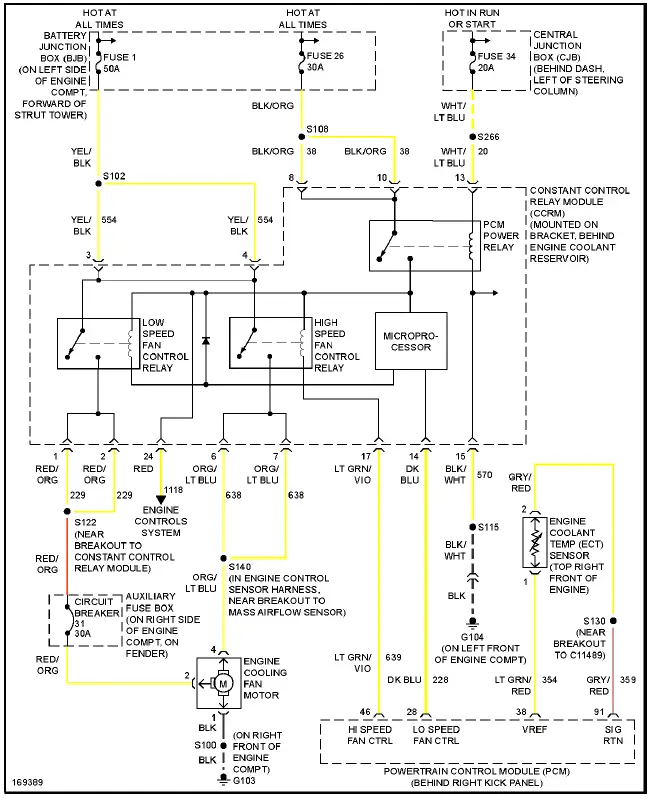
Fig. 8: 4.6L, Cooling Fan Circuit
CRUISE CONTROL
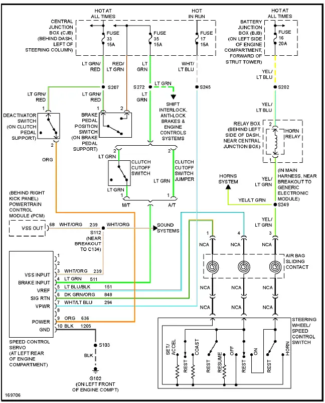
Fig. 9: Cruise Control Circuit
DEFOGGERS
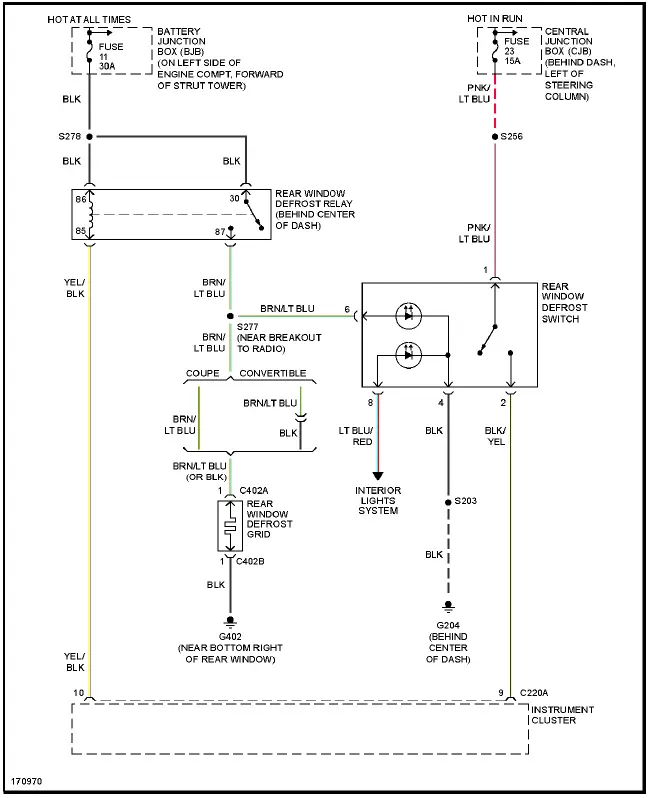
Fig. 10: Defoggers Circuit
ENGINE PERFORMANCE
3.8L
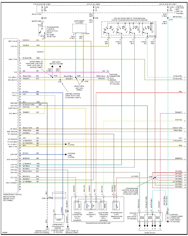
Fig. 11: 3.8L, Engine Performance Circuit (1 of 3)
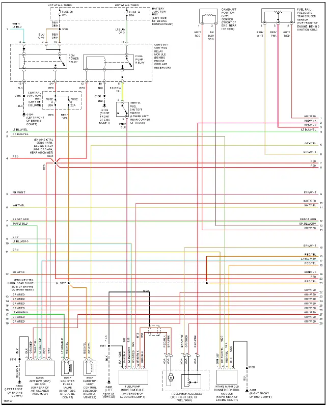
Fig. 12: 3.8L, Engine Performance Circuit (2 of 3)
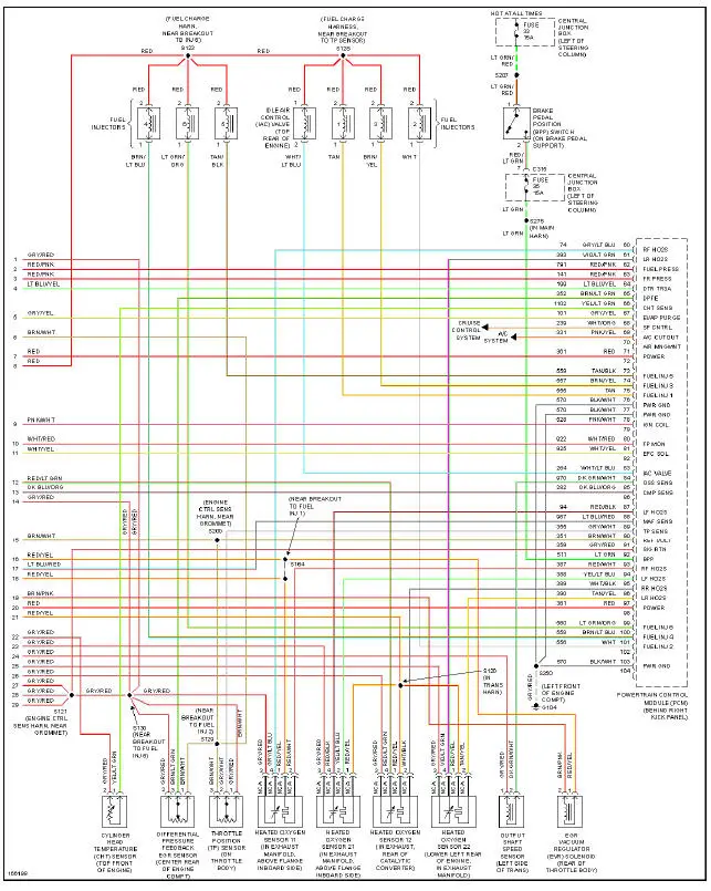
Fig. 13: 3.8L, Engine Performance Circuit (3 of 3)
4.6L DOHC
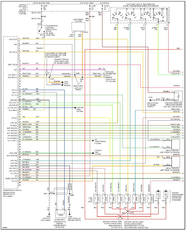
Fig. 14: 4.6L DOHC, Engine Performance Circuit (1 of 3)
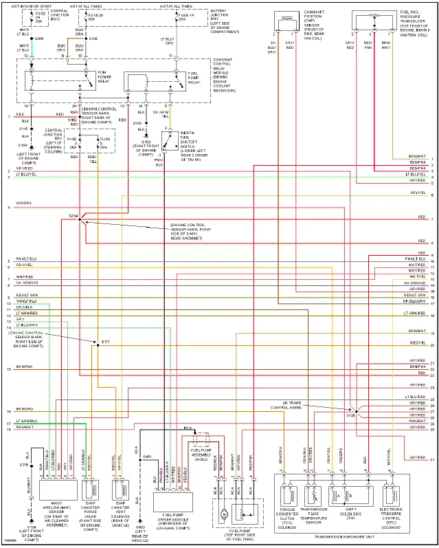
Fig. 15: 4.6L DOHC, Engine Performance Circuit (2 of 3)
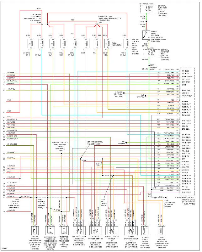
Fig. 16: 4.6L DOHC, Engine Performance Circuit (3 of 3)
4.6L SC
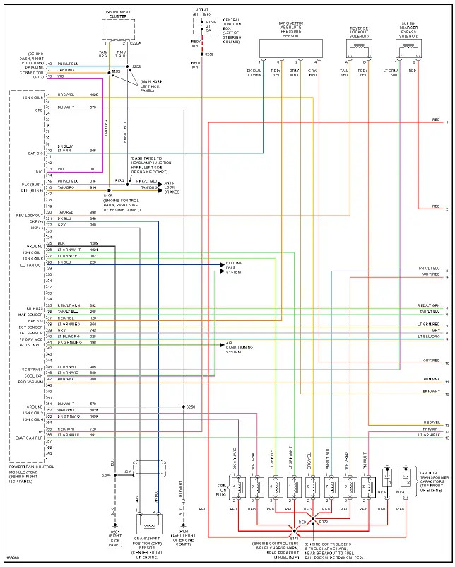
Fig. 17: 4.6L SC, Engine Performance Circuit (1 of 3)
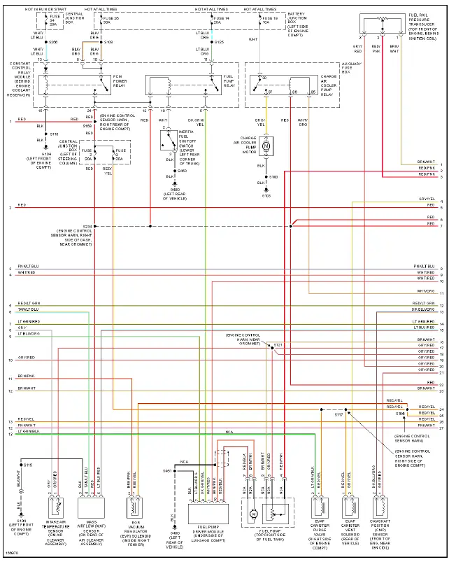
Fig. 18: 4.6L SC, Engine Performance Circuit (2 of 3)
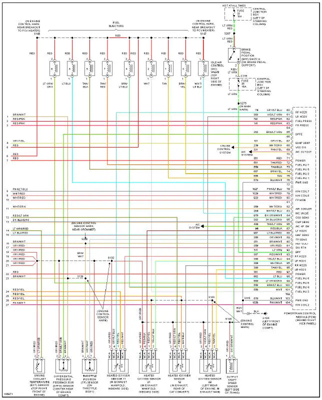
Fig. 19: 4.6L SC, Engine Performance Circuit (3 of 3)
4.6L SOHC
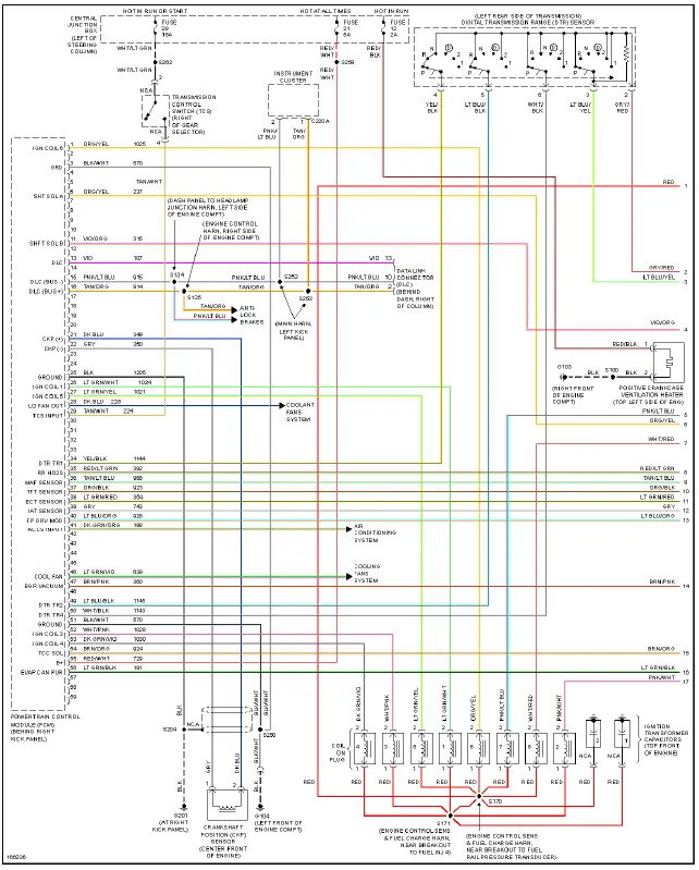
Fig. 20: 4.6L SOHC, Engine Performance Circuit (1 of 3)
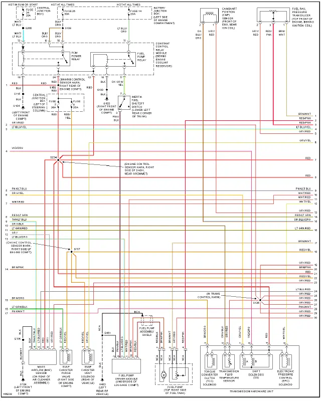
Fig. 21: 4.6L SOHC, Engine Performance Circuit (2 of 3)
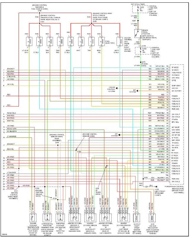
Fig. 22: 4.6L SOHC, Engine Performance Circuit (3 of 3)
EXTERIOR LIGHTS
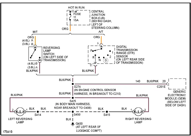
Fig. 23: Back-up Lamps Circuit
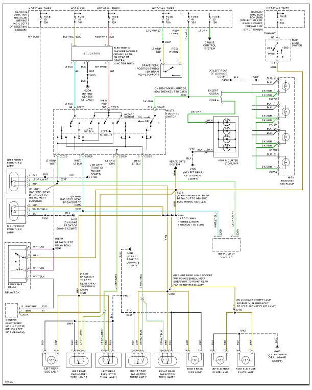
Fig. 24: Exterior Lamps Circuit
GROUND DISTRIBUTION
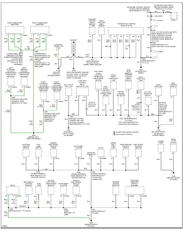
Fig. 25: Ground Distribution Circuit (1 of 2)
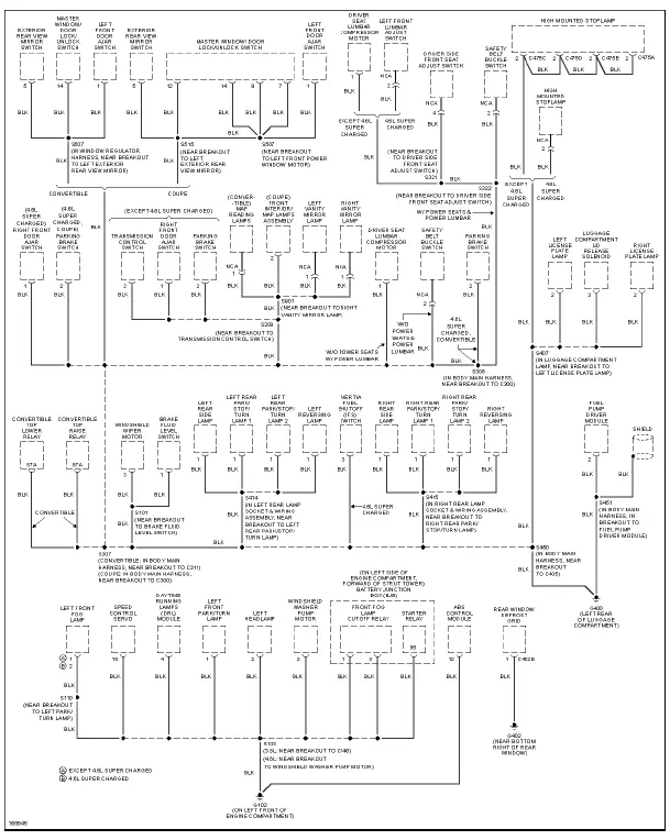
Fig. 26: Ground Distribution Circuit (2 of 2)
HEADLIGHTS
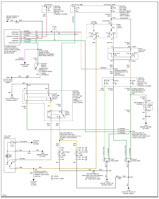
Fig. 27: Headlights Circuit
HORN
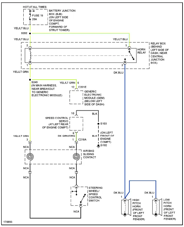
Fig. 28: Horn Circuit
INSTRUMENT CLUSTER
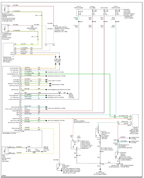
Fig. 29: Instrument Cluster Circuit
INTERIOR LIGHTS
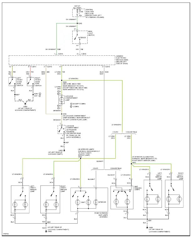
Fig. 30: Courtesy Lamps Circuit
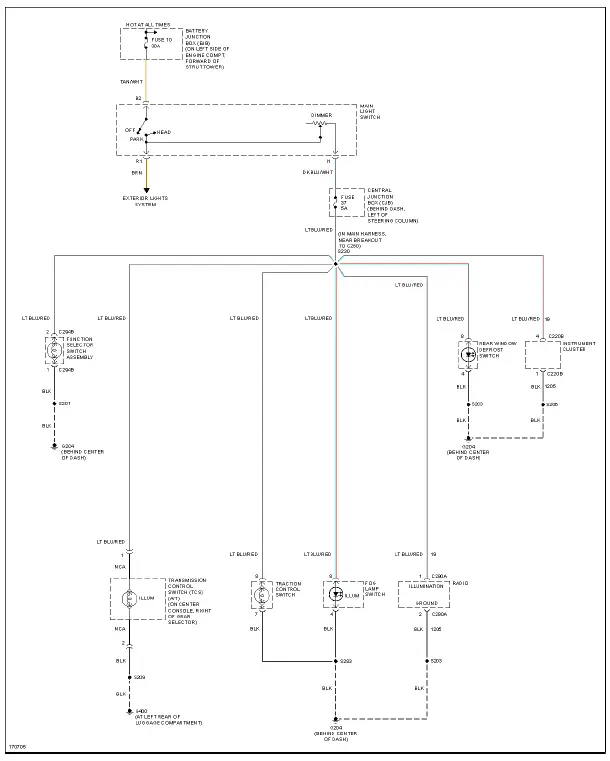
Fig. 31: Instrument Illumination Circuit
POWER DISTRIBUTION
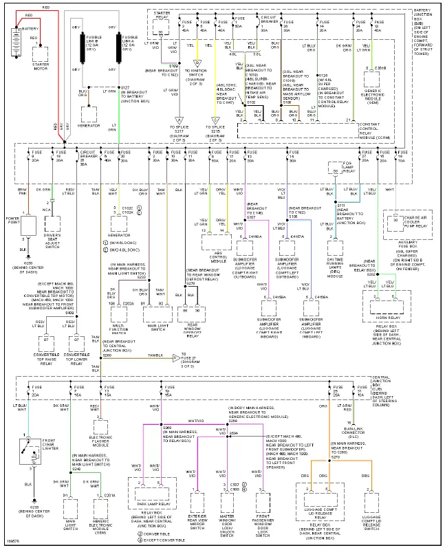
Fig. 32: Power Distribution Circuit (1 of 3)
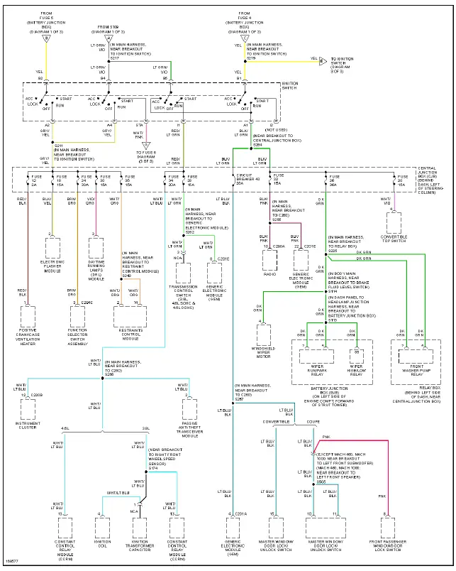
Fig. 33: Power Distribution Circuit (2 of 3)
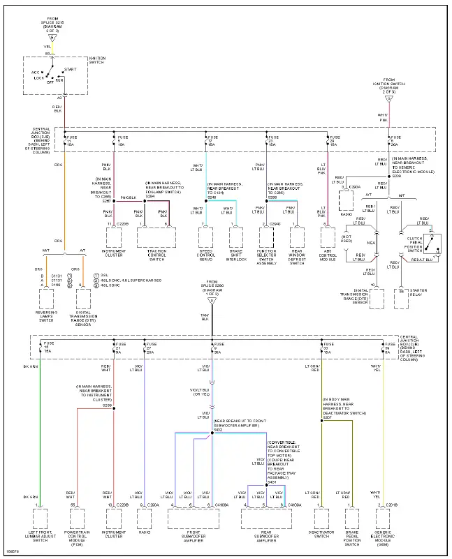
Fig. 34: Power Distribution Circuit (3 of 3)
POWER DOOR LOCKS
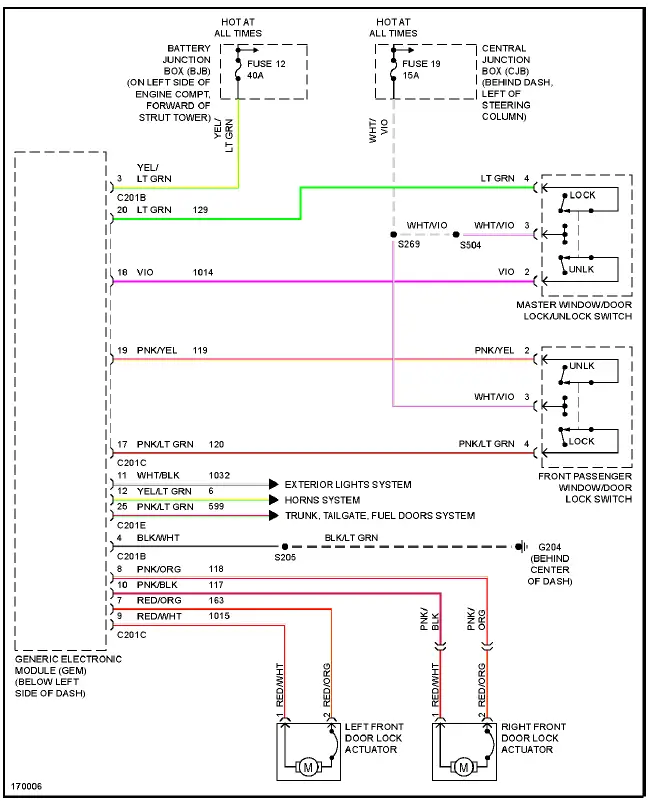
Fig. 35: Power Door Locks Circuit
POWER MIRRORS
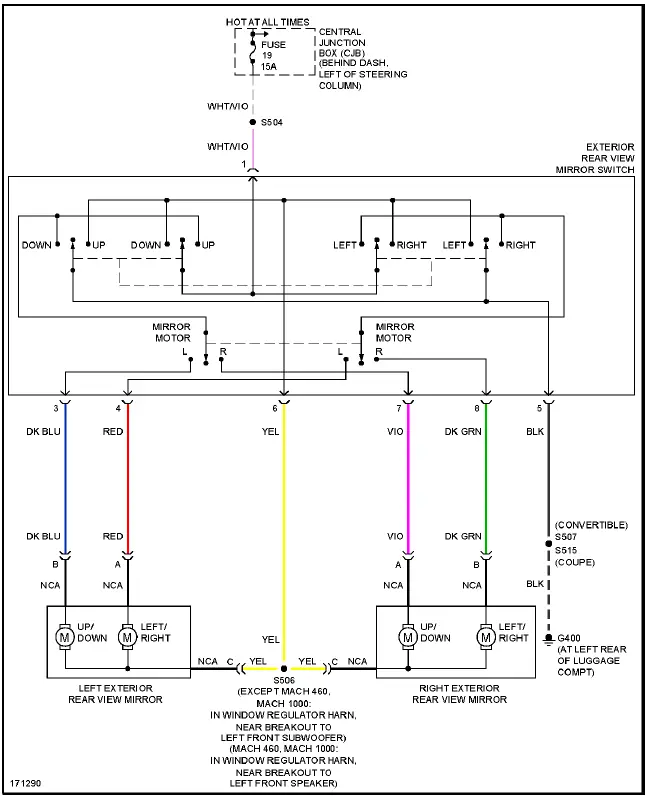
Fig. 36: Power Mirrors Circuit
POWER SEATS
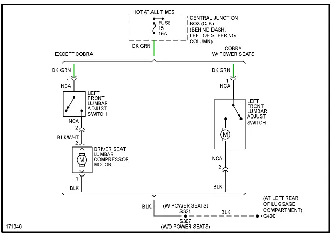
Fig. 37: Lumbar Circuit
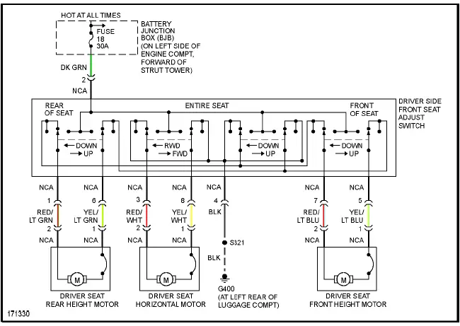
Fig. 38: Power Seat Circuit
POWER TOP/SUNROOF
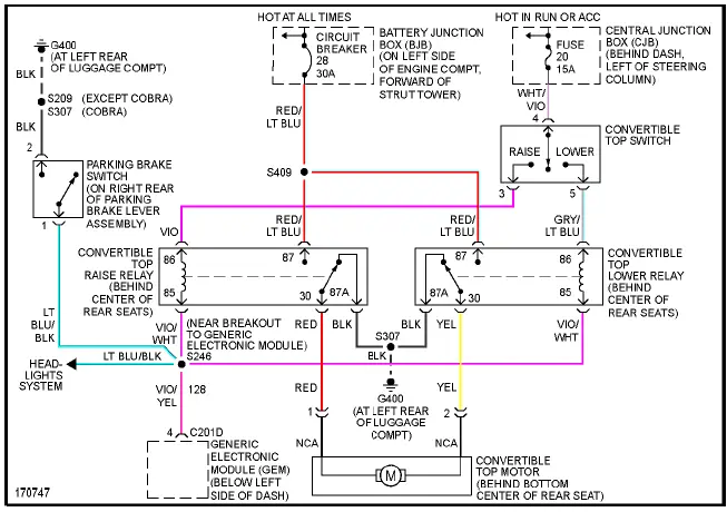
Fig. 39: Power Top/Sunroof Circuit
POWER WINDOWS
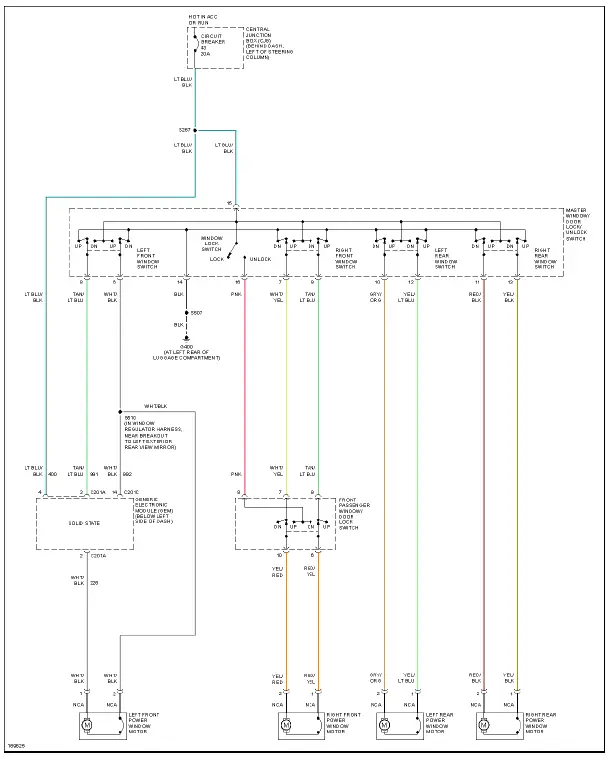
Fig. 40: Power Windows Circuit, Convertible
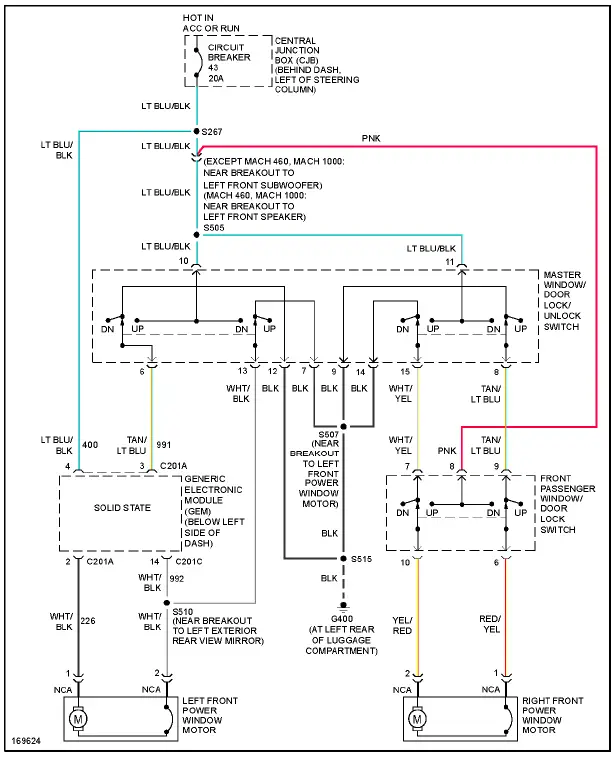
Fig. 41: Power Windows Circuit, Coupe
RADIO
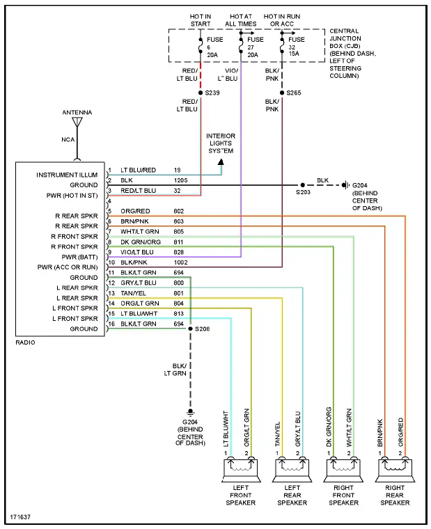
Fig. 42: Base Radio Circuit
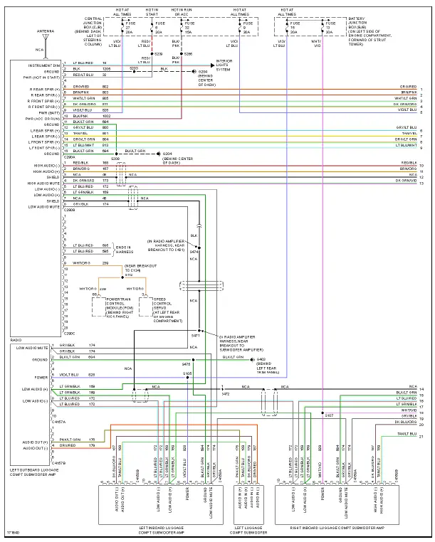
Fig. 43: Premium Sound Radio Circuit, Convertible W/ Mach 1000 Sound System (1 of 2)
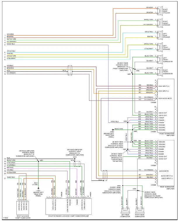
Fig. 44: Premium Sound Radio Circuit, Convertible W/ Mach 1000 Sound System (2 of 2)
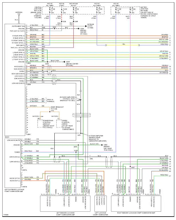
Fig. 45: Premium Sound Radio Circuit, Coupe W/ Mach 1000 Sound System (1 of 2)
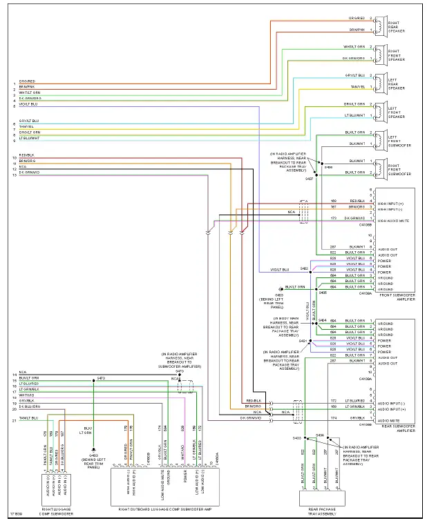
Fig. 46: Premium Sound Radio Circuit, Coupe W/ Mach 1000 Sound System (2 of 2)
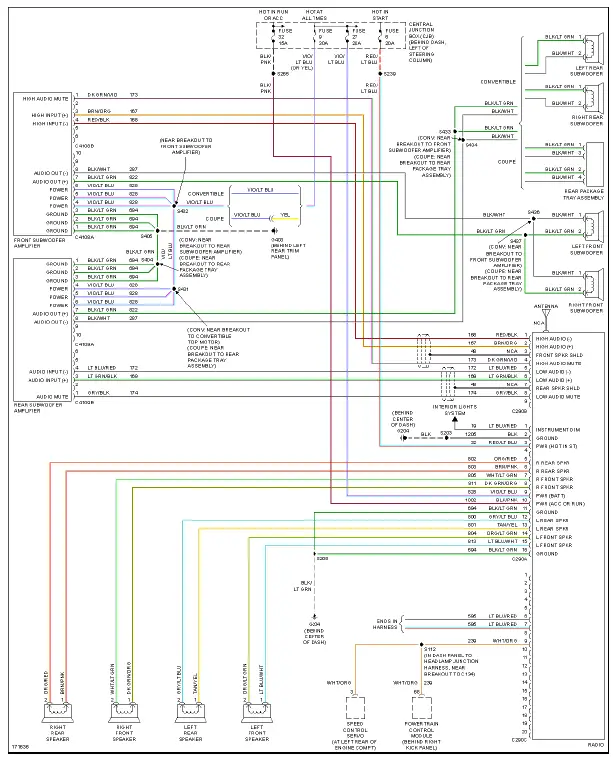
Fig. 47: Premium Sound Radio Circuit, W/ Mach 460 Sound System
SHIFT INTERLOCK
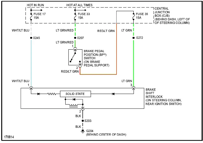
Fig. 48: Shift Interlock Circuit
STARTING/CHARGING
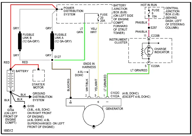
Fig. 49: Charging Circuit
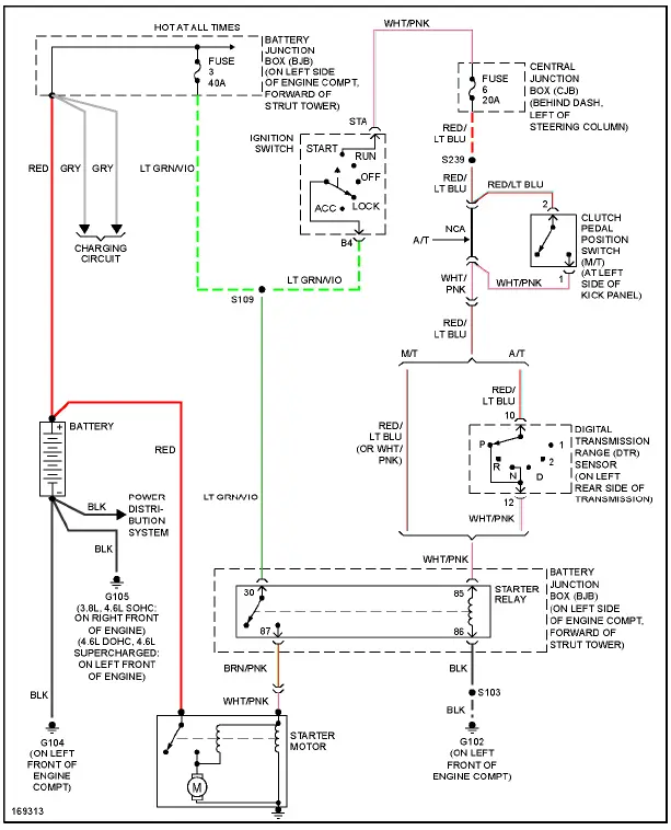
Fig. 50: Starting Circuit
SUPPLEMENTAL RESTRAINTS
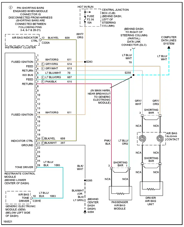
Fig. 51: Supplemental Restraints Circuit
TRANSMISSION
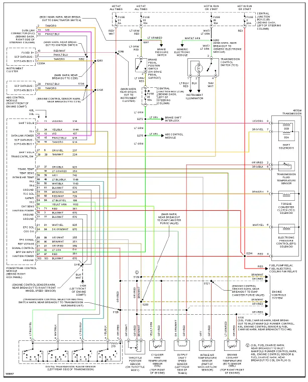
Fig. 52: A/T Circuit
TRUNK, TAILGATE, FUEL DOOR
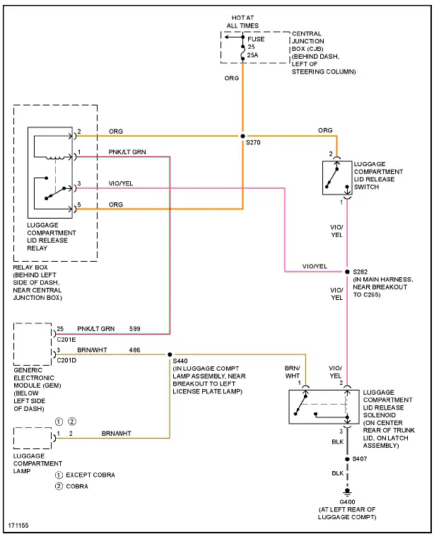
Fig. 53: Trunk, Tailgate, Fuel Door Circuit
WARNING SYSTEMS
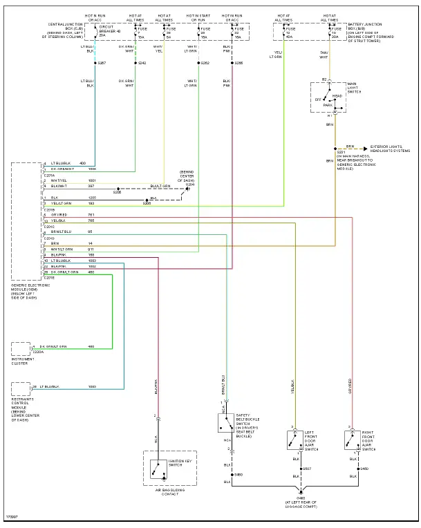
Fig. 54: Warning Systems Circuit
WIPER/WASHER
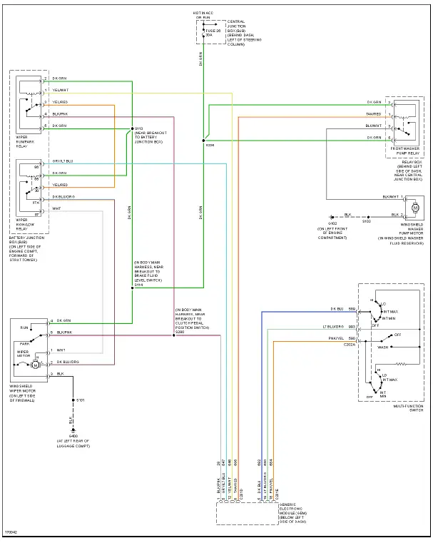
Fig. 55: Wiper/Washer Circuit
USING WIRING DIAGRAMS
For information on using these wiring diagrams, see USING SYSTEM WIRING DIAGRAMS article.
AIR CONDITIONING
3.8L
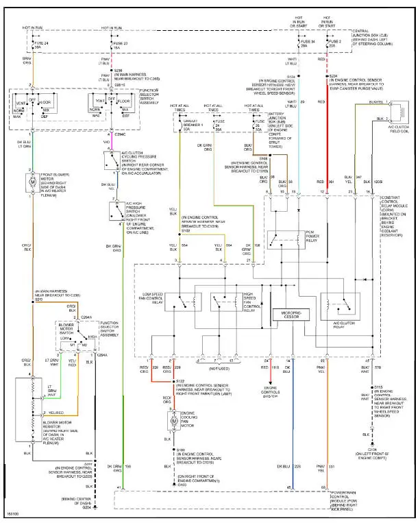
Fig. 1: 3.8L, Air Conditioning Circuit
4.6L
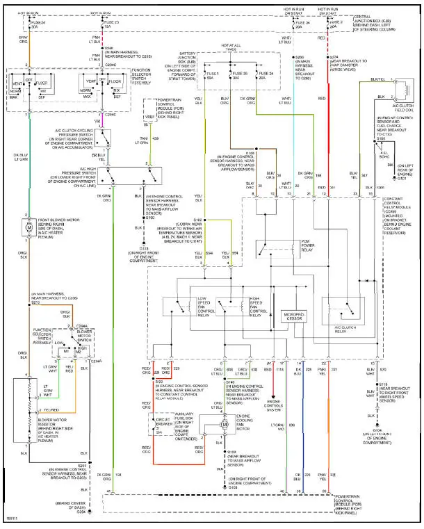
Fig. 2: 4.6L, Air Conditioning Circuit
ANTI-LOCK BRAKES
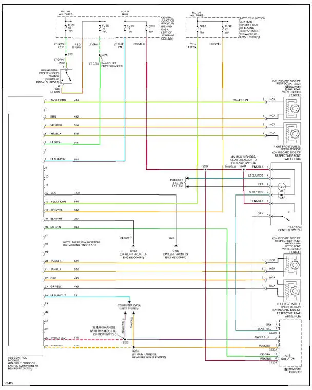
Fig. 3: Anti-lock Brakes Circuit
ANTI-THEFT
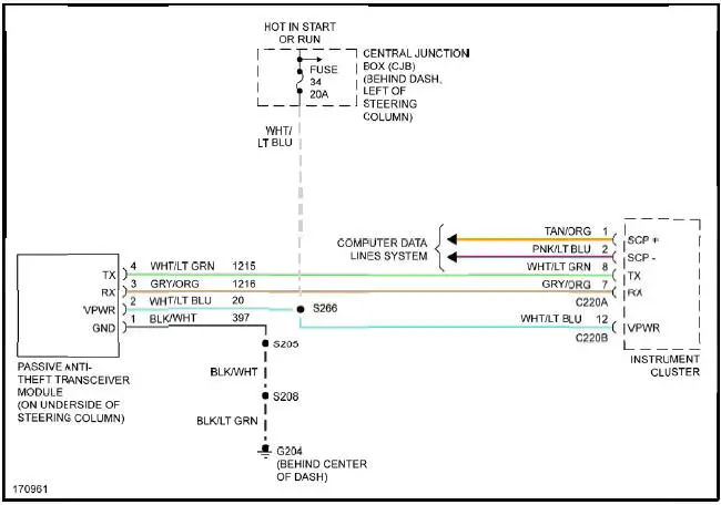
Fig. 4: Passive Anti-theft Circuit
BODY CONTROL MODULES
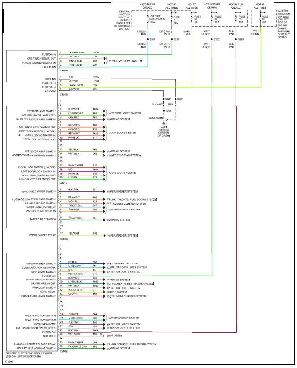
Fig. 5: Body Control Modules Circuit
COMPUTER DATA LINES
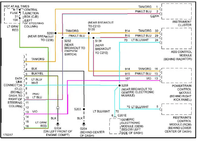
Fig. 6: Computer Data Lines Circuit
COOLING FAN
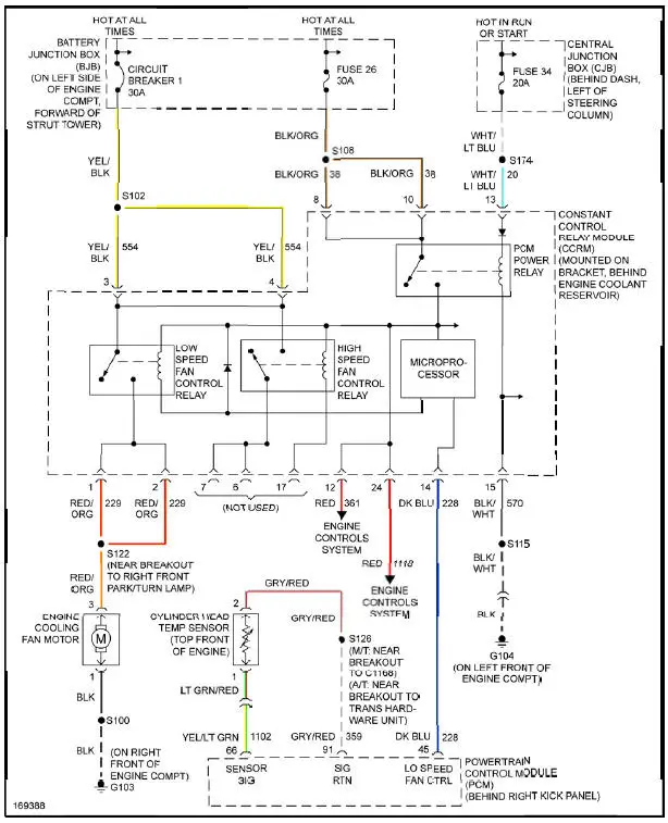
Fig. 7: 3.8L, Cooling Fan Circuit
4.6L
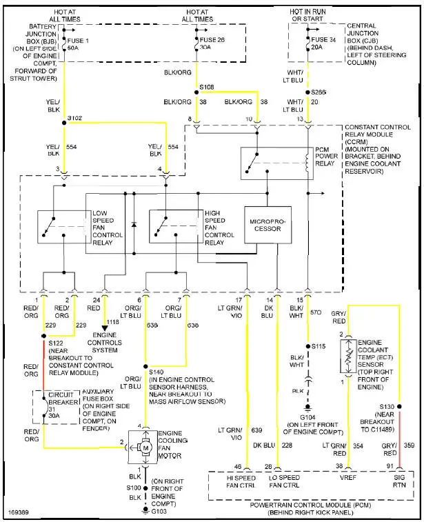
Fig. 8: 4.6L, Cooling Fan Circuit
CRUISE CONTROL
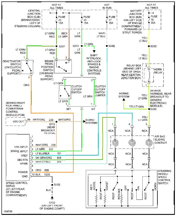
Fig. 9: Cruise Control Circuit
DEFOGGERS
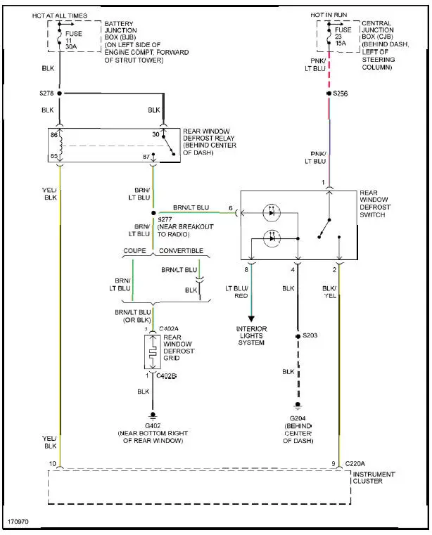
Fig. 10: Defoggers Circuit
ENGINE PERFORMANCE
3.8L

Fig. 11: 3.8L, Engine Performance Circuit (1 of 3)

Fig. 12: 3.8L, Engine Performance Circuit (2 of 3)
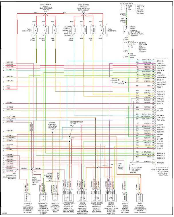
Fig. 13: 3.8L, Engine Performance Circuit (3 of 3)
4.6L DOHC

Fig. 14: 4.6L DOHC, Engine Performance Circuit (1 of 3)
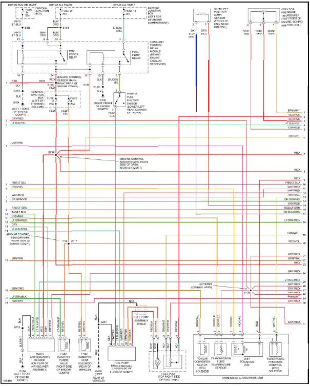
Fig. 15: 4.6L DOHC, Engine Performance Circuit (2 of 3)
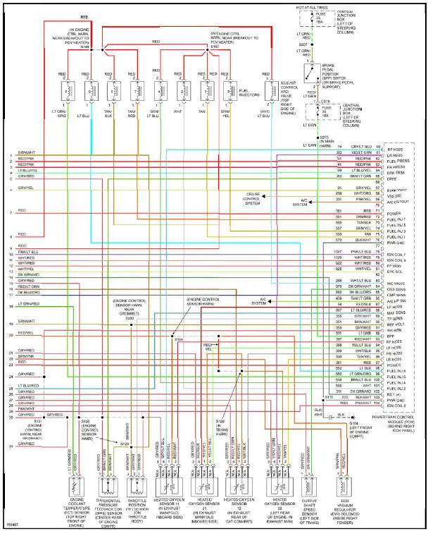
Fig. 16: 4.6L DOHC, Engine Performance Circuit (3 of 3)
4.6L SC
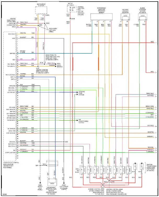
Fig. 17: 4.6L SC, Engine Performance Circuit (1 of 3)
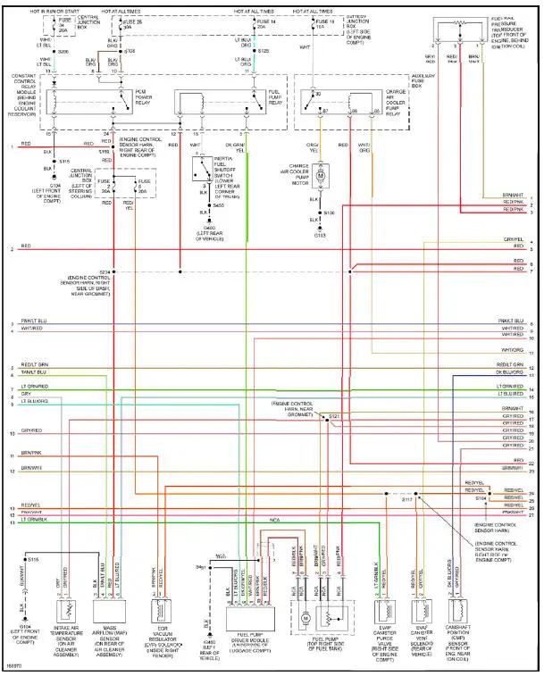
Fig. 18: 4.6L SC, Engine Performance Circuit (2 of 3)
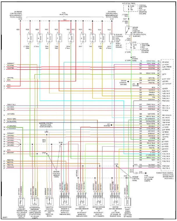
Fig. 19: 4.6L SC, Engine Performance Circuit (3 of 3)
4.6L SOHC
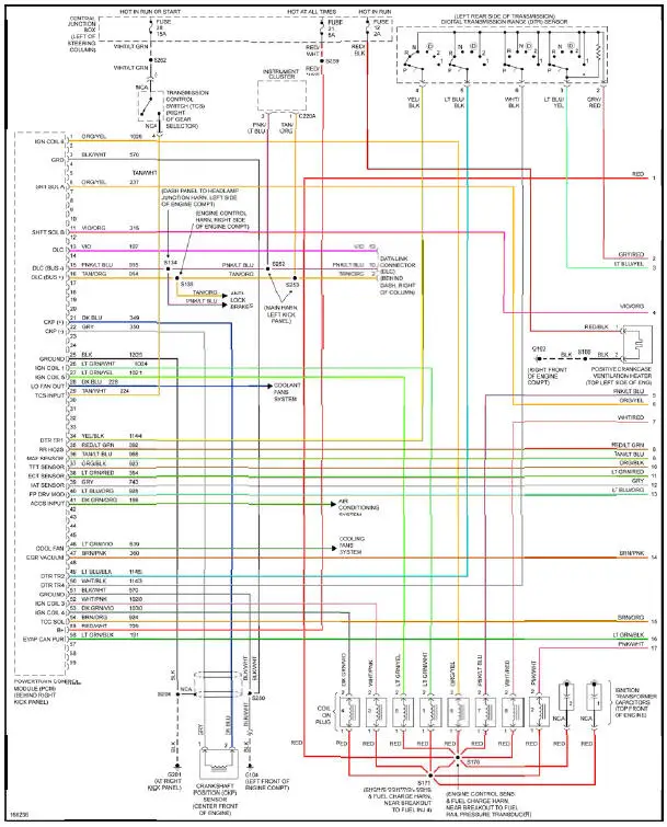
Fig. 20: 4.6L SOHC, Engine Performance Circuit (1 of 3)
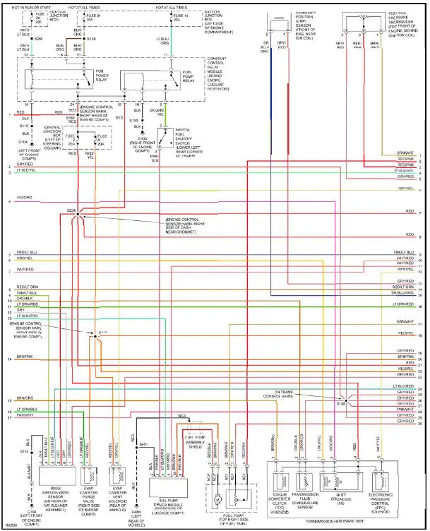
Fig. 21: 4.6L SOHC, Engine Performance Circuit (2 of 3)
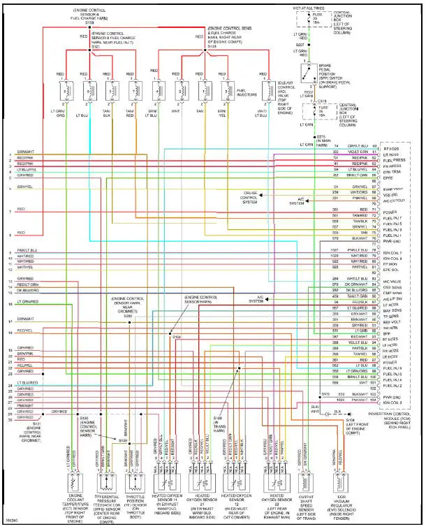
Fig. 22: 4.6L SOHC, Engine Performance Circuit (3 of 3)
EXTERIOR LIGHTS
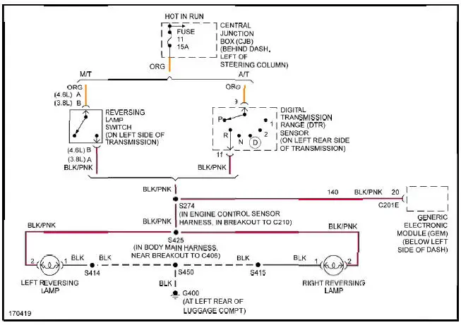
Fig. 23: Back-up Lamps Circuit
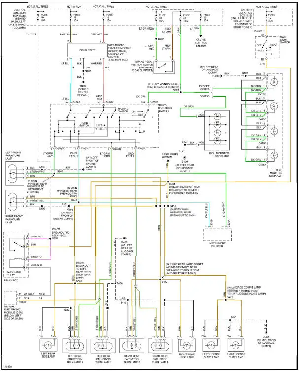
Fig. 24: Exterior Lamps Circuit
GROUND DISTRIBUTION
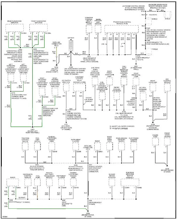
Fig. 25: Ground Distribution Circuit (1 of 2)
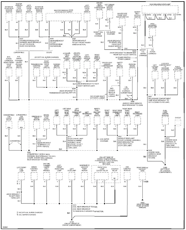
Fig. 26: Ground Distribution Circuit (2 of 2)
HEADLIGHTS
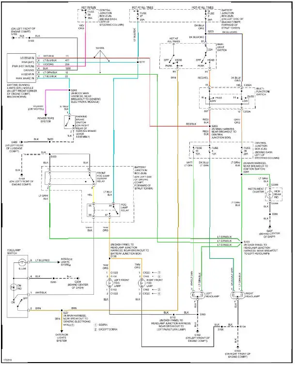
Fig. 27: Headlights Circuit
HORN
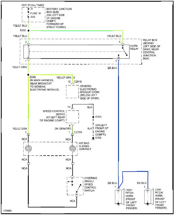
Fig. 28: Horn Circuit
INSTRUMENT CLUSTER
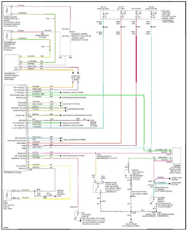
Fig. 29: Instrument Cluster Circuit
INTERIOR LIGHTS
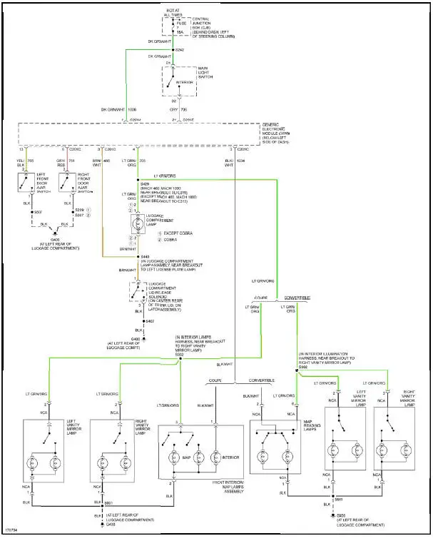
Fig. 30: Courtesy Lamps Circuit
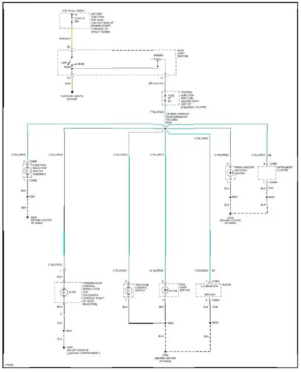
Fig. 31: Instrument Illumination Circuit
POWER DISTRIBUTION
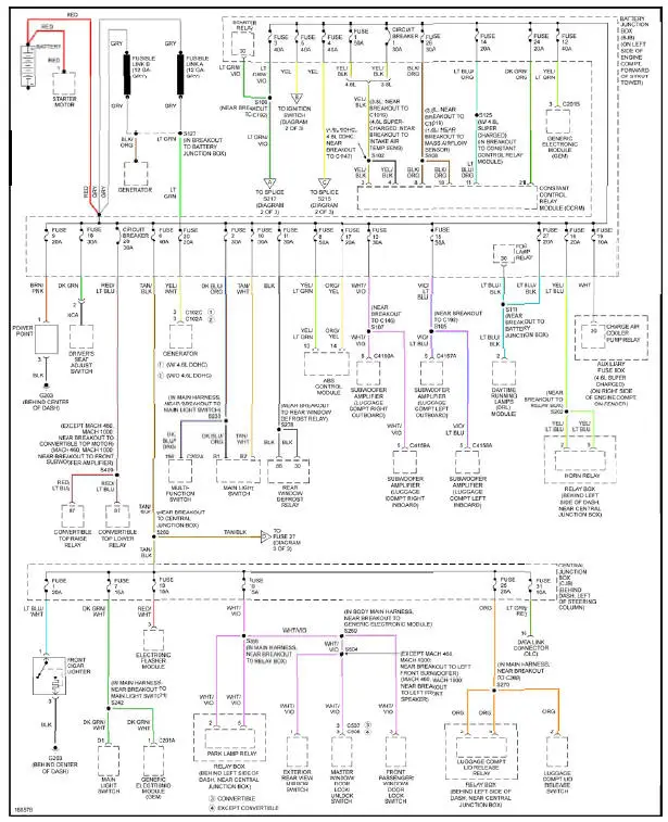
Fig. 32: Power Distribution Circuit (1 of 3)
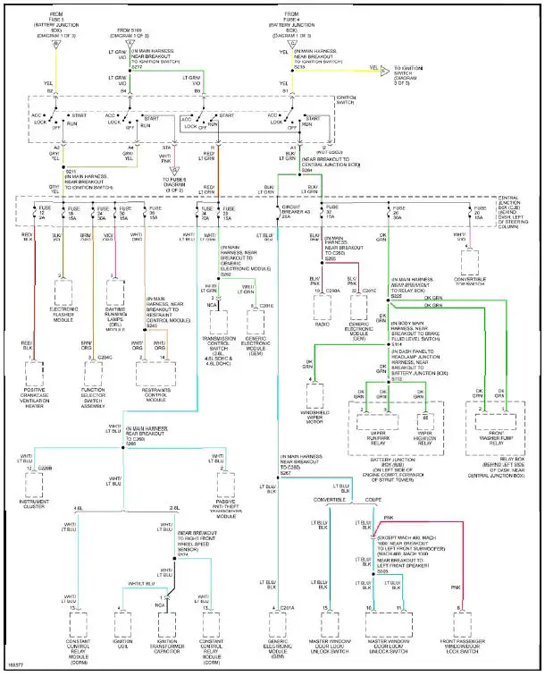
Fig. 33: Power Distribution Circuit (2 of 3)
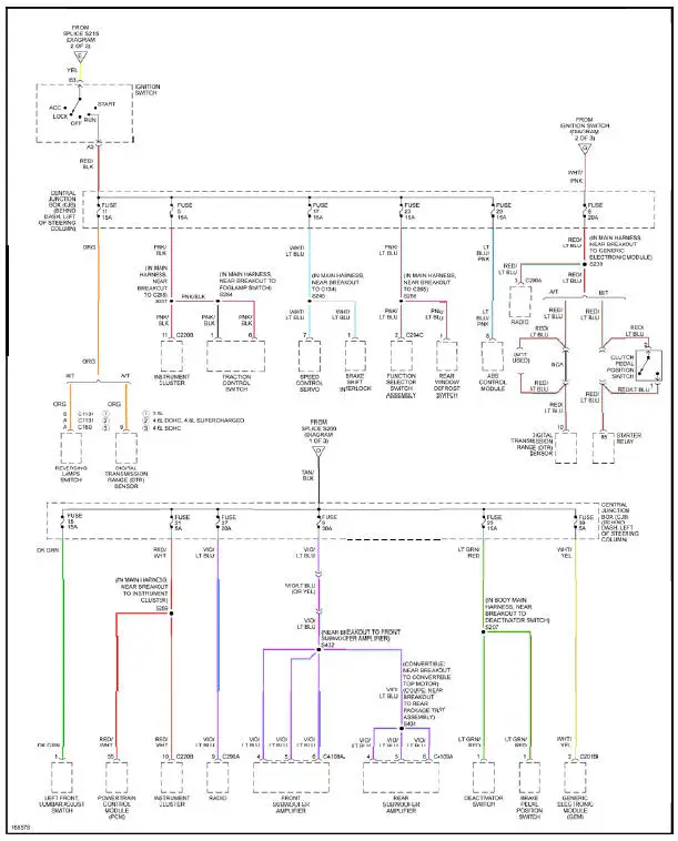
Fig. 34: Power Distribution Circuit (3 of 3)
POWER DOOR LOCKS
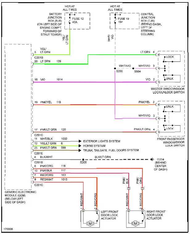
Fig. 35: Power Door Locks Circuit
POWER MIRRORS
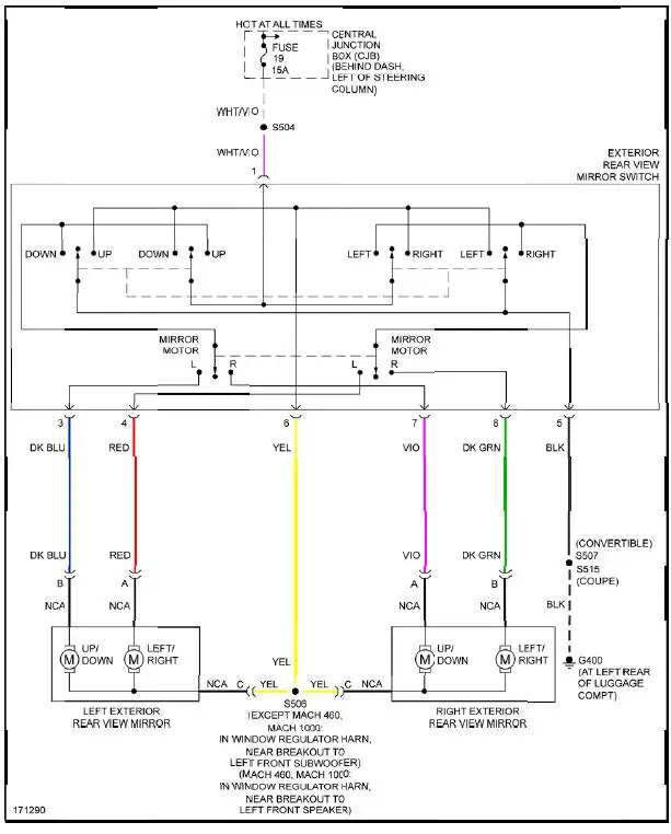
Fig. 36: Power Mirrors Circuit
POWER SEATS
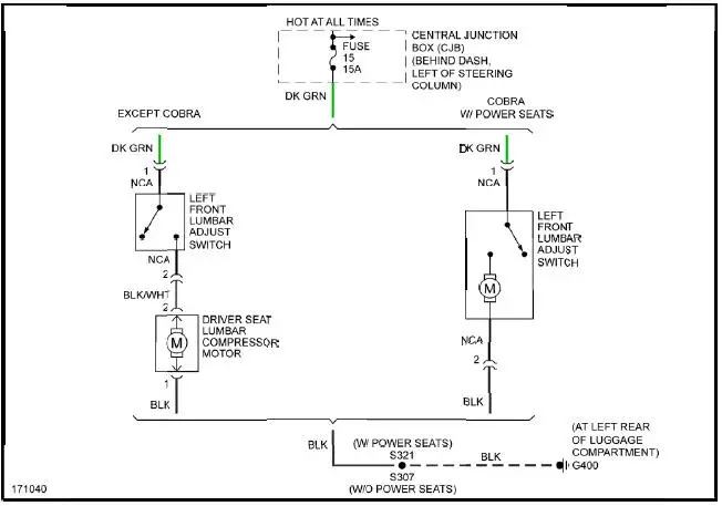
Fig. 37: Lumbar Circuit

Fig. 38: Power Seat Circuit
POWER TOP/SUNROOF
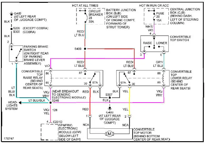
Fig. 39: Power Top/Sunroof Circuit
POWER WINDOWS
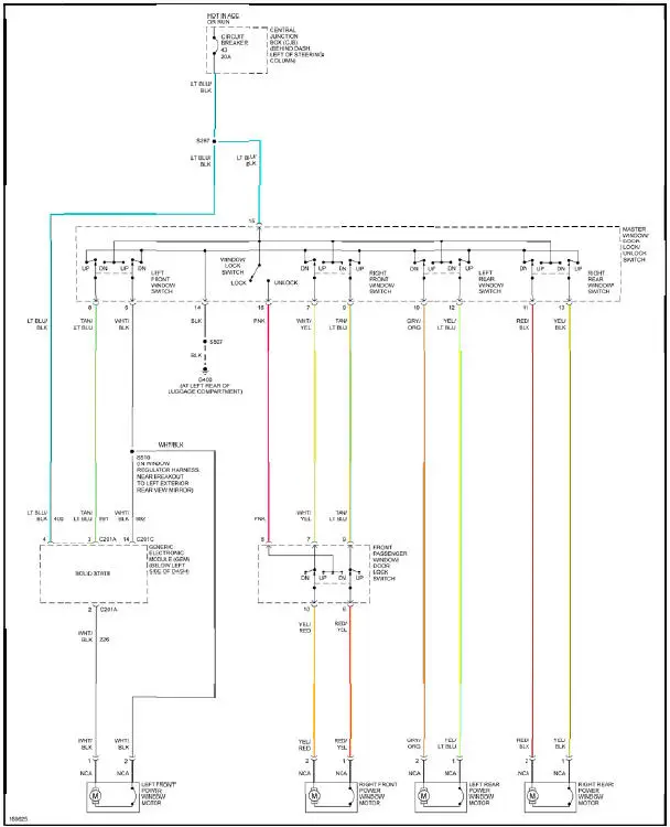
Fig. 40: Power Windows Circuit, Convertible
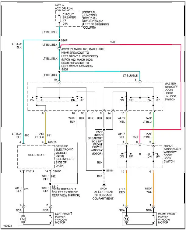
Fig. 41: Power Windows Circuit, Coupe
RADIO
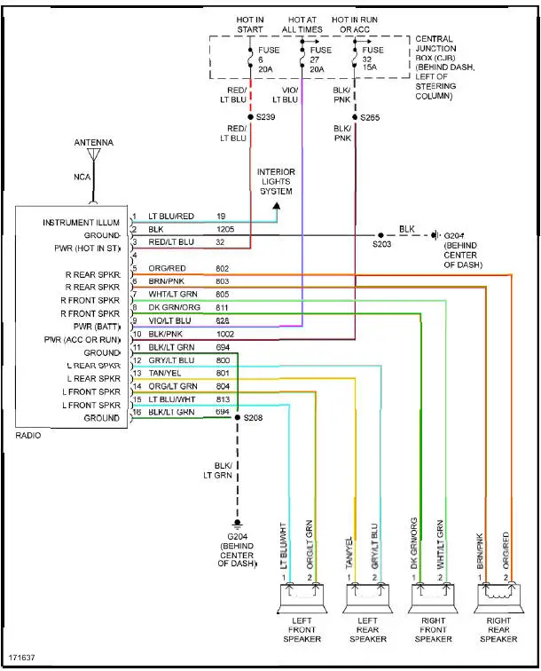
Fig. 42: Base Radio Circuit
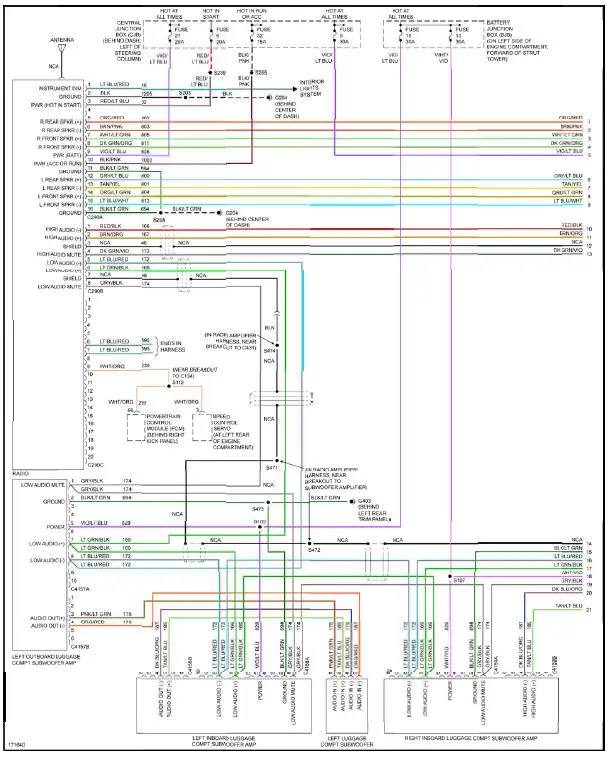
Fig. 43: Premium Sound Radio Circuit, Convertible W/ Mach 1000 Sound System (1 of 2)
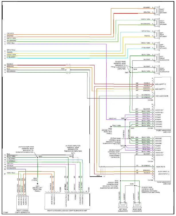
Fig. 44: Premium Sound Radio Circuit, Convertible W/ Mach 1000 Sound System (2 of 2)
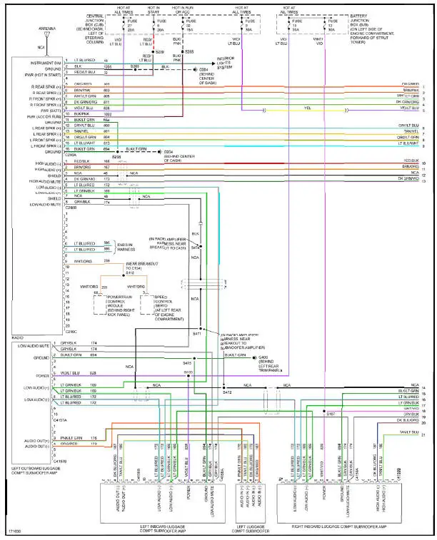
Fig. 45: Premium Sound Radio Circuit, Coupe W/ Mach 1000 Sound System (1 of 2)
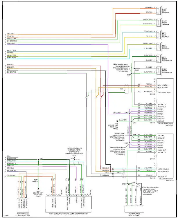
Fig. 46: Premium Sound Radio Circuit, Coupe W/ Mach 1000 Sound System (2 of 2)
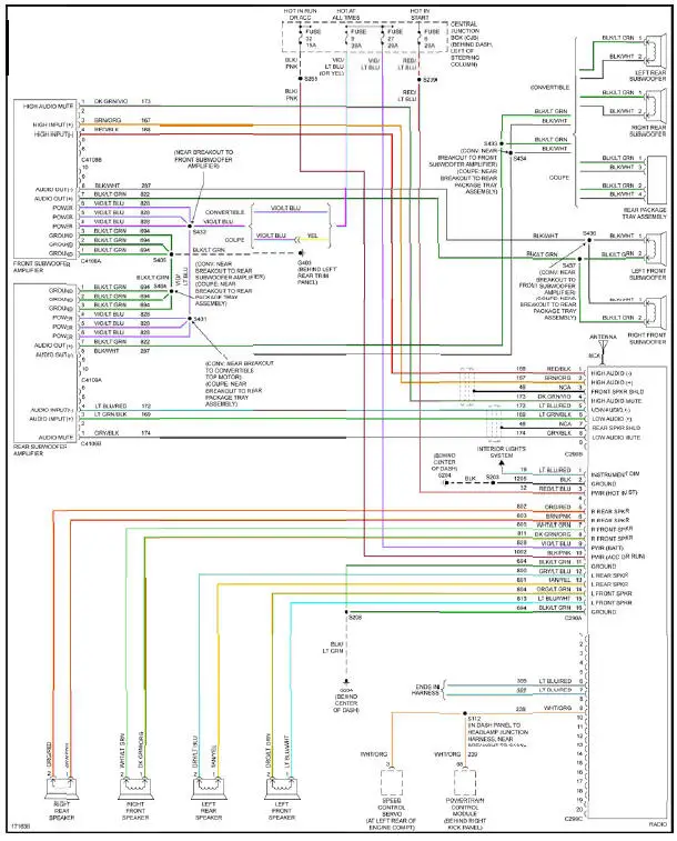
Fig. 47: Premium Sound Radio Circuit, W/ Mach 460 Sound System
SHIFT INTERLOCK
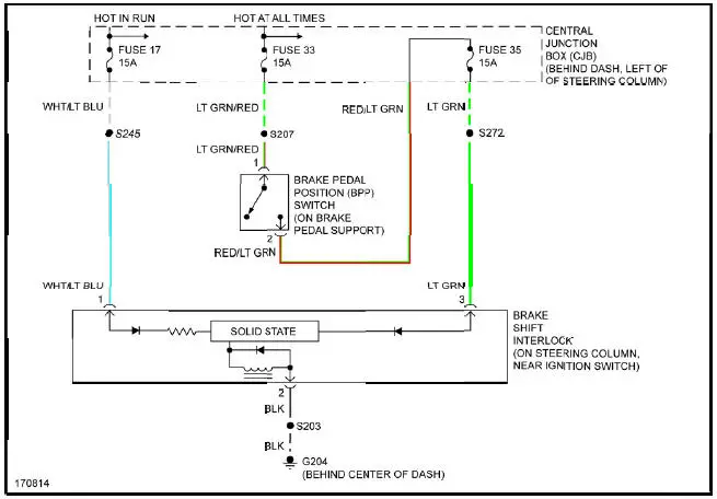
Fig. 48: Shift Interlock Circuit
STARTING/CHARGING
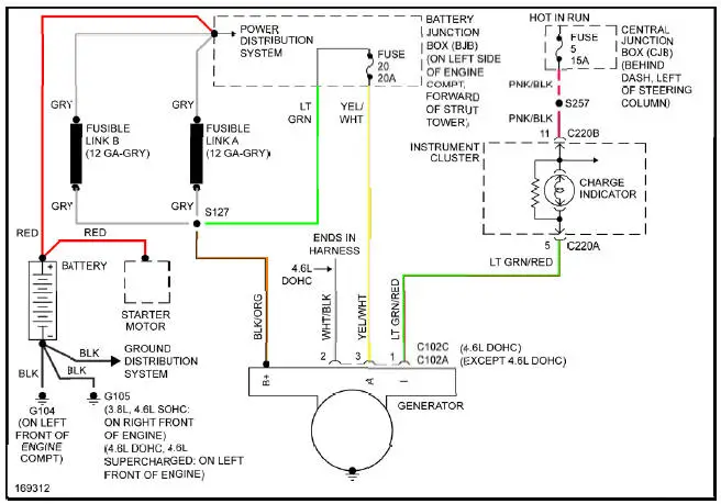
Fig. 49: Charging Circuit
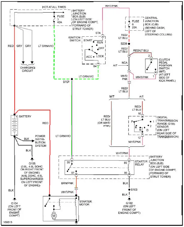
Fig. 50: Starting Circuit
SUPPLEMENTAL RESTRAINTS
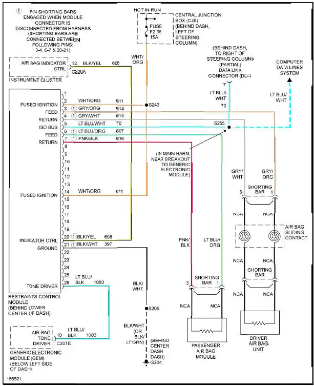
Fig. 51: Supplemental Restraints Circuit
TRANSMISSION
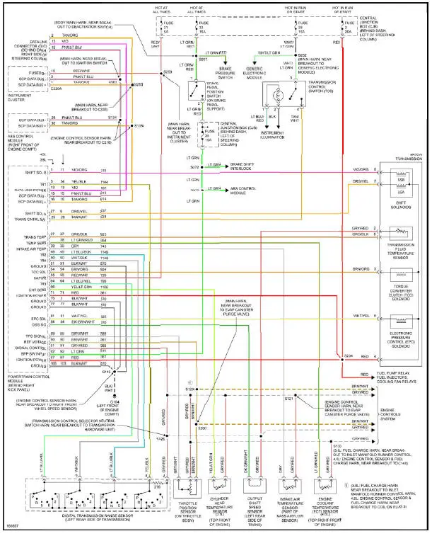
Fig. 52: A/T Circuit
TRUNK, TAILGATE, FUEL DOOR
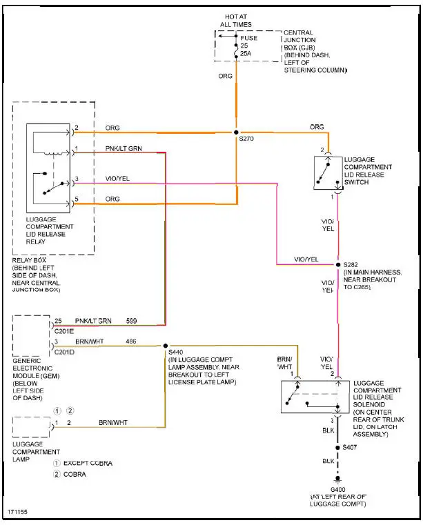
Fig. 53: Trunk, Tailgate, Fuel Door Circuit
WARNING SYSTEMS
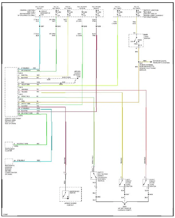
Fig. 54: Warning Systems Circuit
WIPER/WASHER
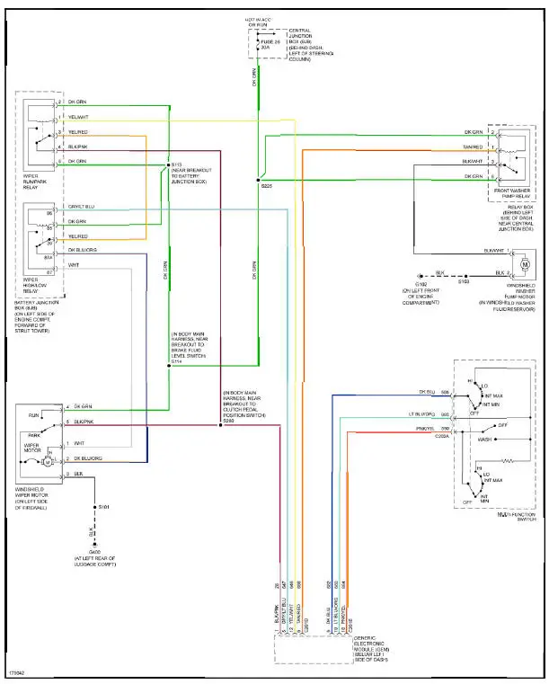
Fig. 55: Wiper/Washer Circuit
USING WIRING DIAGRAMS
For information on using these wiring diagrams, see USING SYSTEM WIRING DIAGRAMS article.
AIR CONDITIONING
3.8L
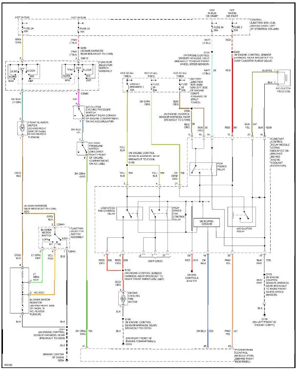
Fig. 1: 3.8L, Air Conditioning Circuit
4.6L
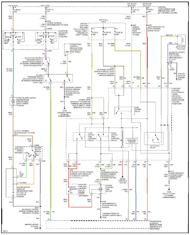
Fig. 2: 4.6L, Air Conditioning Circuit
ANTI-LOCK BRAKES
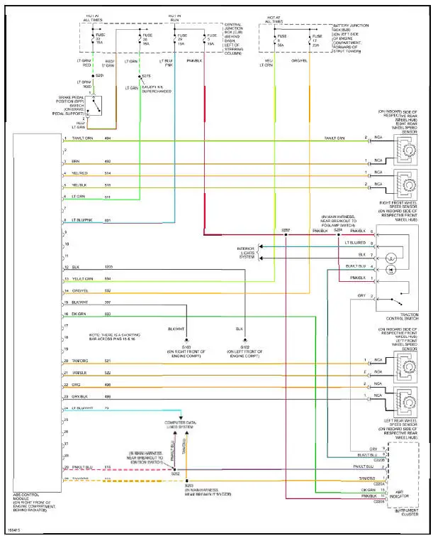
Fig. 3: Anti-lock Brakes Circuit
ANTI-THEFT
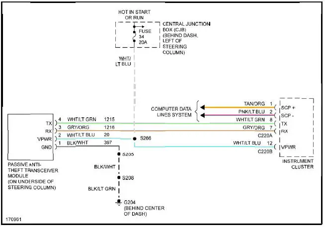
Fig. 4: Passive Anti-theft Circuit
BODY CONTROL MODULES
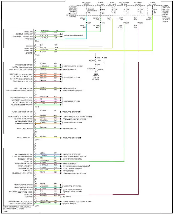
Fig. 5: Body Control Modules Circuit
COMPUTER DATA LINES
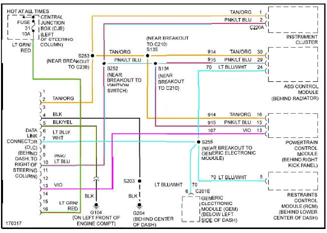
Fig. 6: Computer Data Lines Circuit
COOLING FAN
3.8L
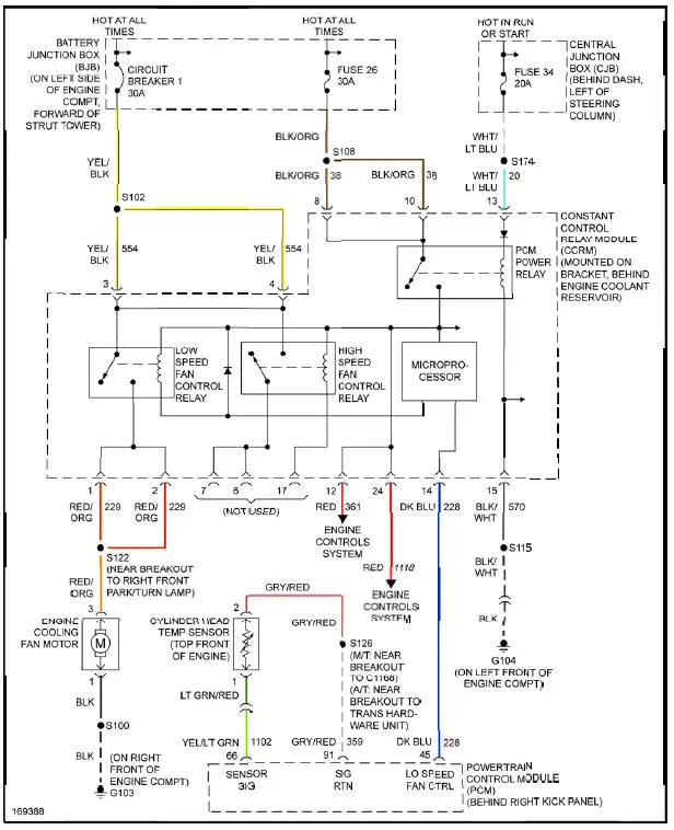
Fig. 7: 3.8L, Cooling Fan Circuit
4.6L
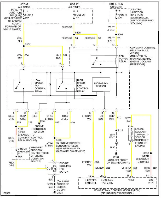
Fig. 8: 4.6L, Cooling Fan Circuit
CRUISE CONTROL
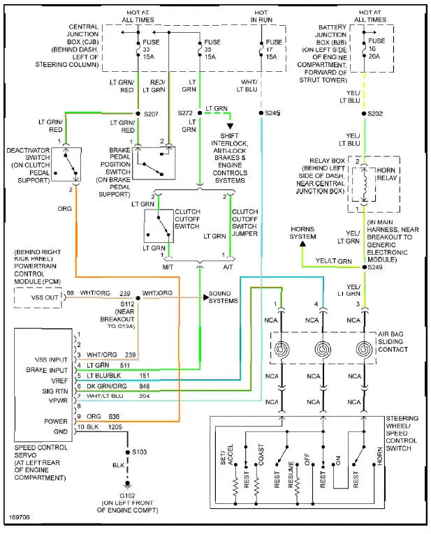
Fig. 9: Cruise Control Circuit
DEFOGGERS
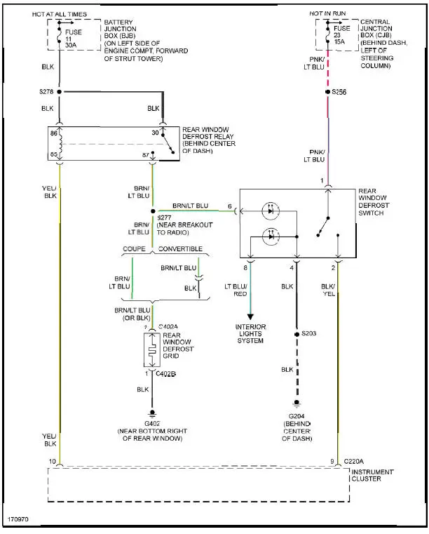
Fig. 10: Defoggers Circuit
ENGINE PERFORMANCE
3.8L
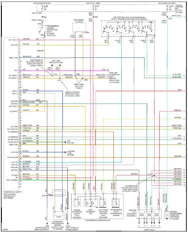
Fig. 11: 3.8L, Engine Performance Circuit (1 of 3)
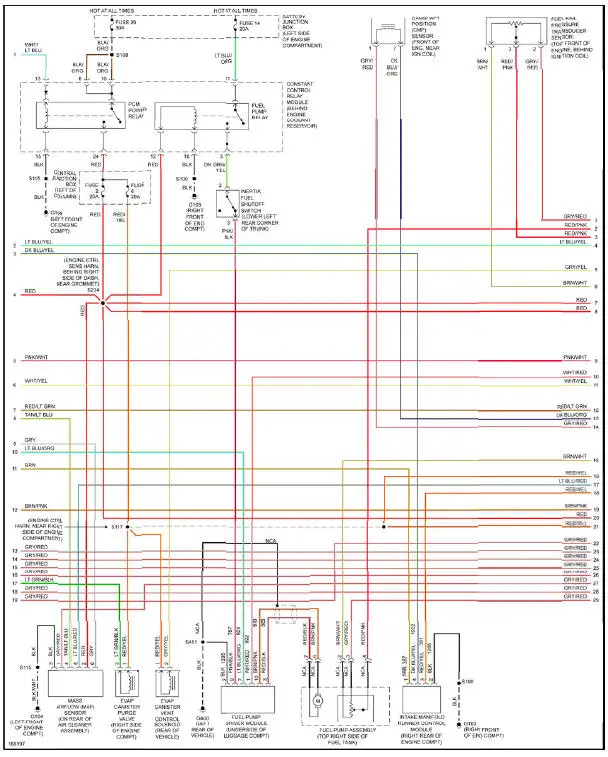
Fig. 12: 3.8L, Engine Performance Circuit (2 of 3)
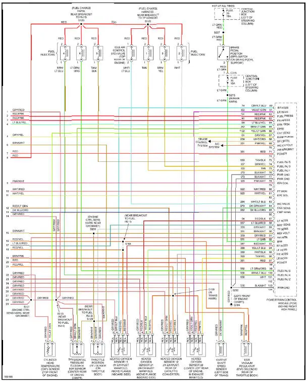
Fig. 13: 3.8L, Engine Performance Circuit (3 of 3)
4.6L DOHC
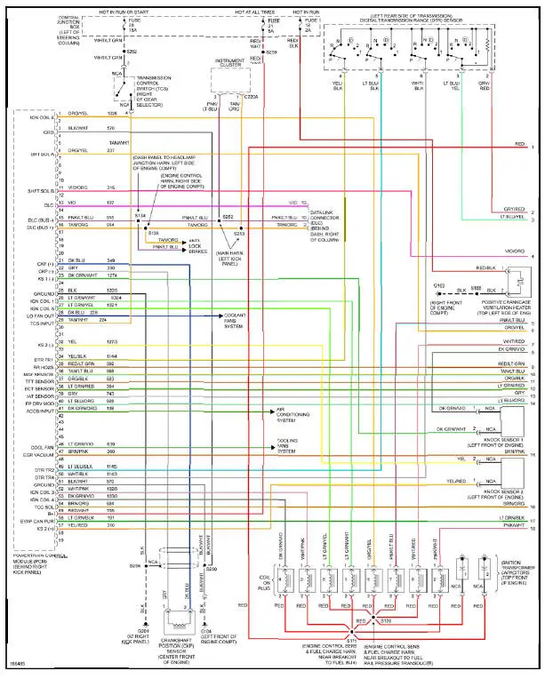
Fig. 14: 4.6L DOHC, Engine Performance Circuit (1 of 3)
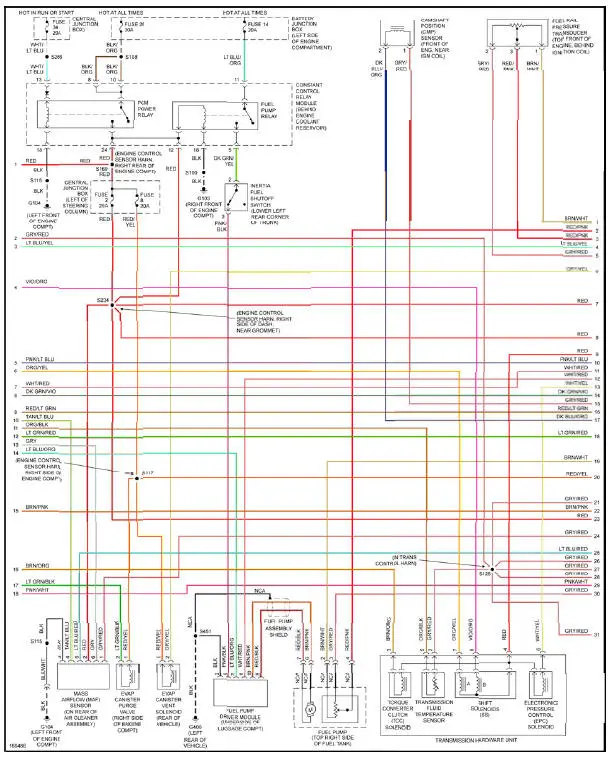
Fig. 15: 4.6L DOHC, Engine Performance Circuit (2 of 3)
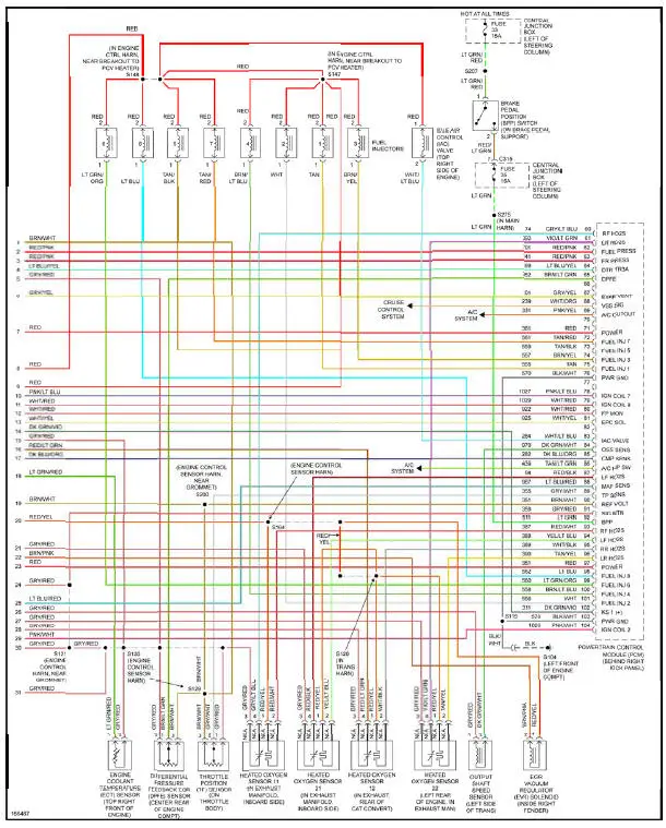
Fig. 16: 4.6L DOHC, Engine Performance Circuit (3 of 3)
4.6L SC

Fig. 17: 4.6L SC, Engine Performance Circuit (1 of 3)
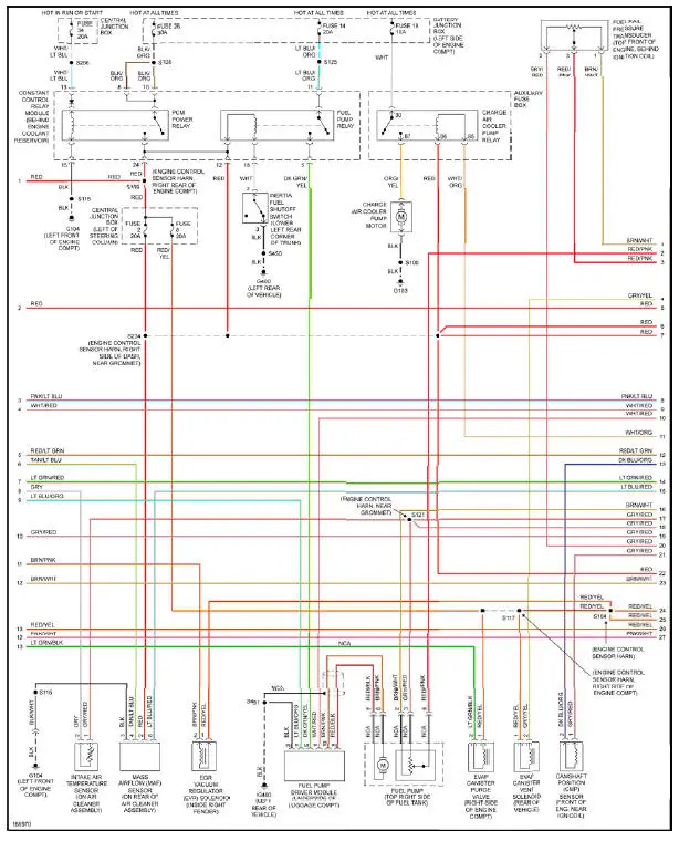
Fig. 18: 4.6L SC, Engine Performance Circuit (2 of 3)
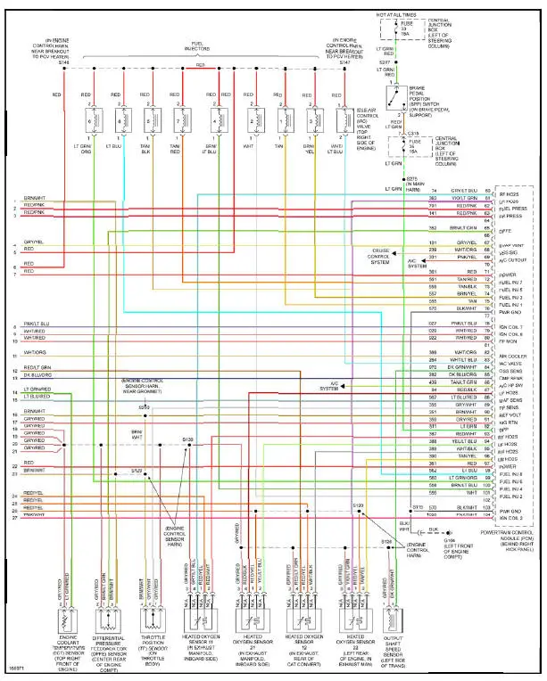
Fig. 19: 4.6L SC, Engine Performance Circuit (3 of 3)
4.6L SOHC

Fig. 20: 4.6L SOHC, Engine Performance Circuit (1 of 3)
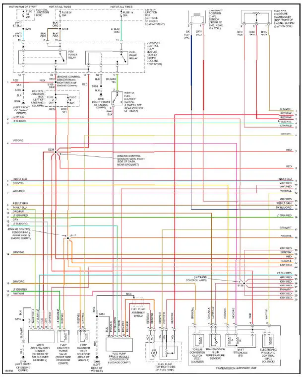
Fig. 21: 4.6L SOHC, Engine Performance Circuit (2 of 3)
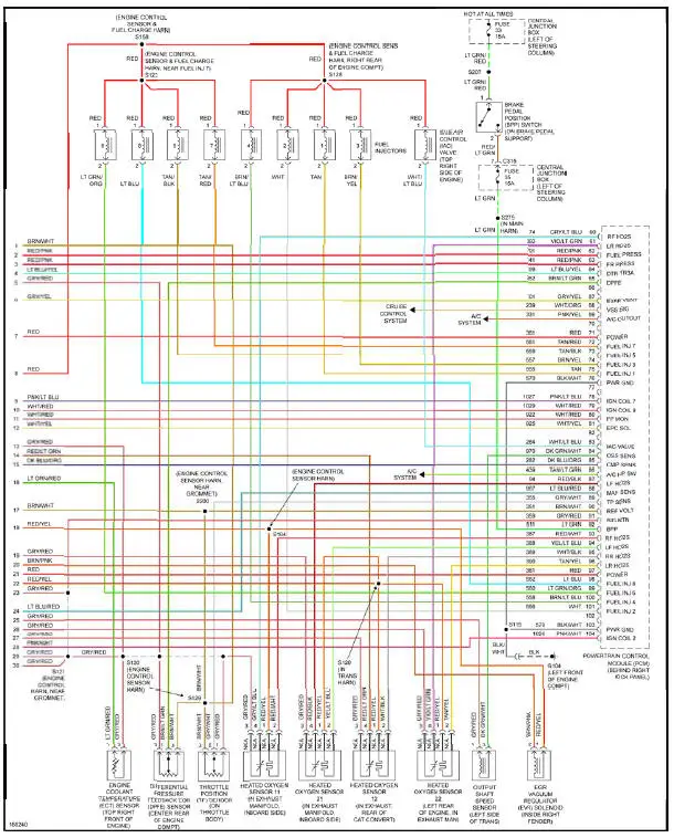
Fig. 22: 4.6L SOHC, Engine Performance Circuit (3 of 3)
EXTERIOR LIGHTS

Fig. 23: Back-up Lamps Circuit
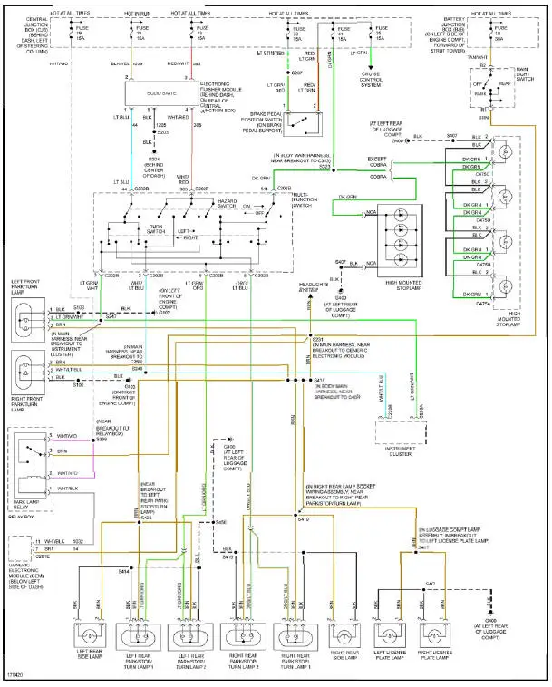
Fig. 24: Exterior Lamps Circuit
GROUND DISTRIBUTION
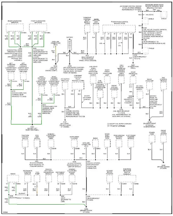
Fig. 25: Ground Distribution Circuit (1 of 2)
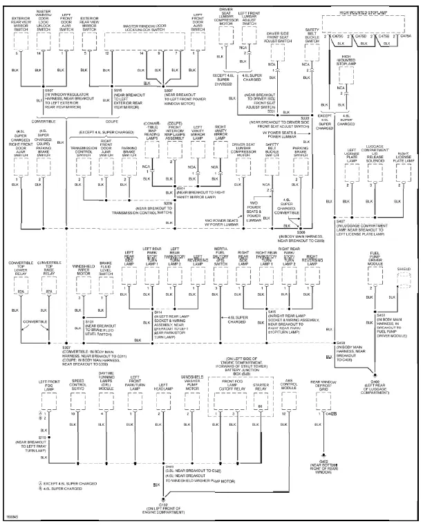
Fig. 26: Ground Distribution Circuit (2 of 2)
HEADLIGHTS
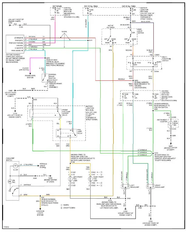
Fig. 27: Headlights Circuit
HORN

Fig. 28: Horn Circuit
INSTRUMENT CLUSTER
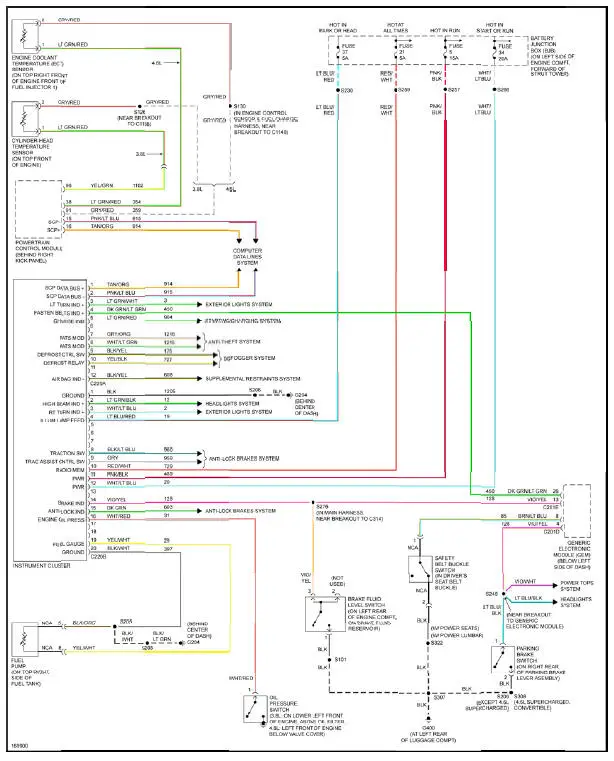
Fig. 29: Instrument Cluster Circuit
INTERIOR LIGHTS
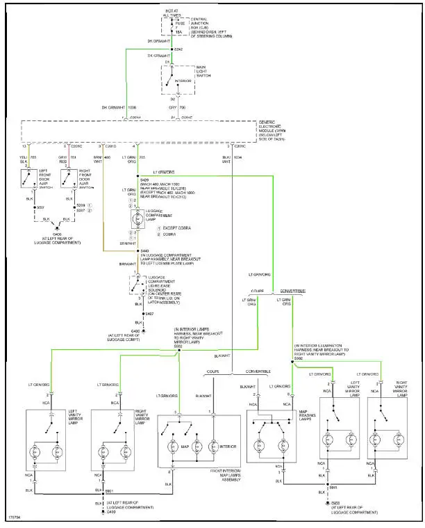
Fig. 30: Courtesy Lamps Circuit
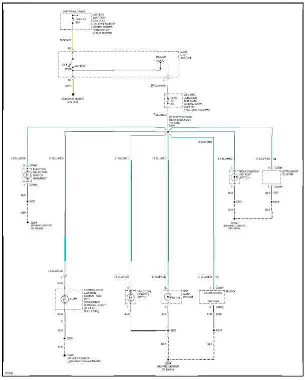
Fig. 31: Instrument Illumination Circuit
POWER DISTRIBUTION
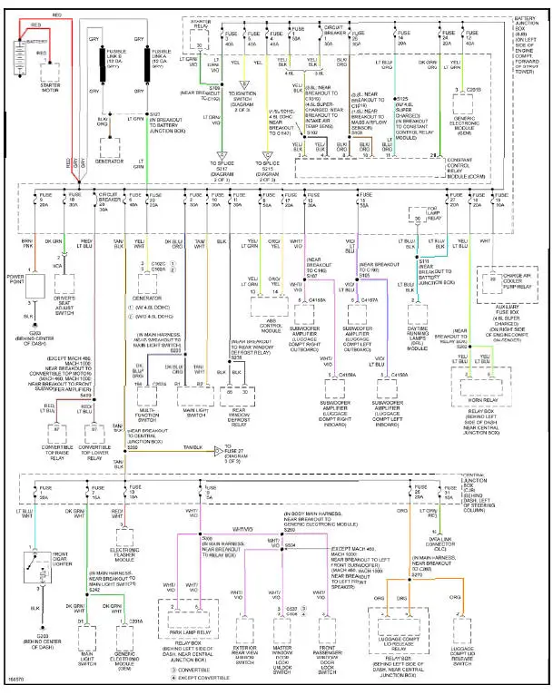
Fig. 32: Power Distribution Circuit (1 of 3)

Fig. 33: Power Distribution Circuit (2 of 3)
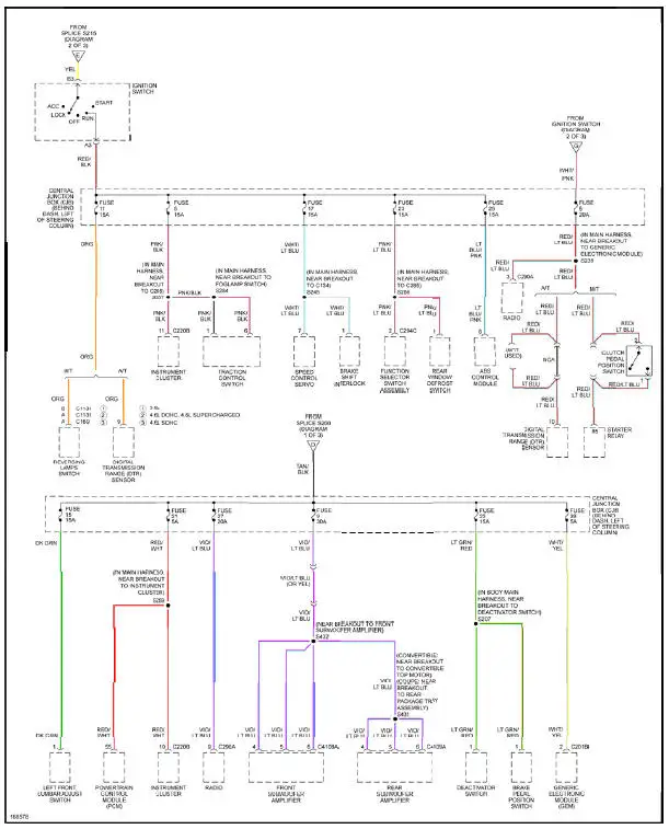
Fig. 34: Power Distribution Circuit (3 of 3)
POWER DOOR LOCKS
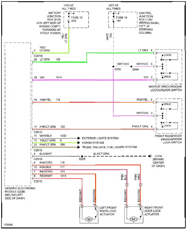
Fig. 35: Power Door Locks Circuit
POWER MIRRORS
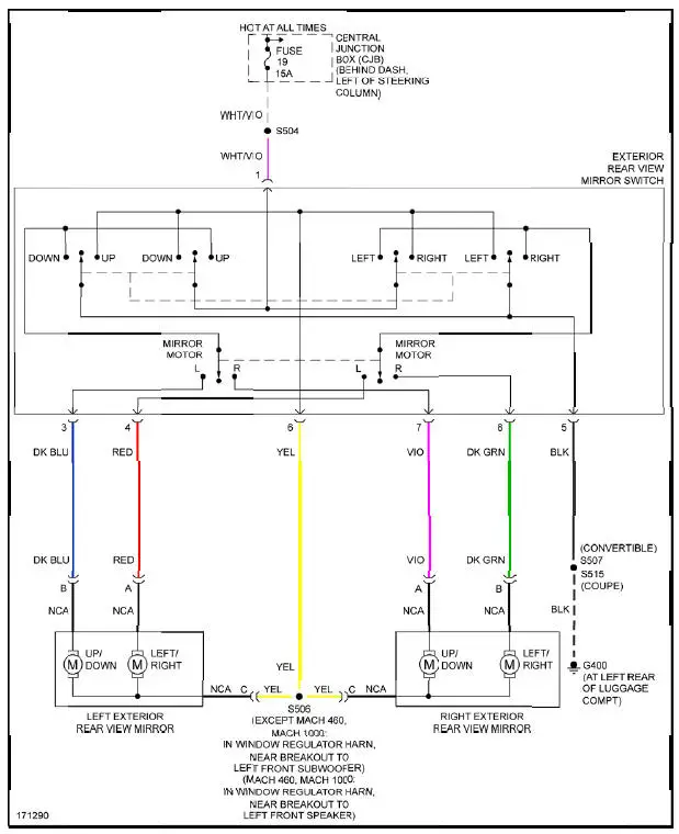
Fig. 36: Power Mirrors Circuit
POWER SEATS
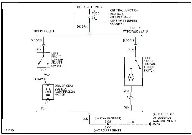
Fig. 37: Lumbar Circuit
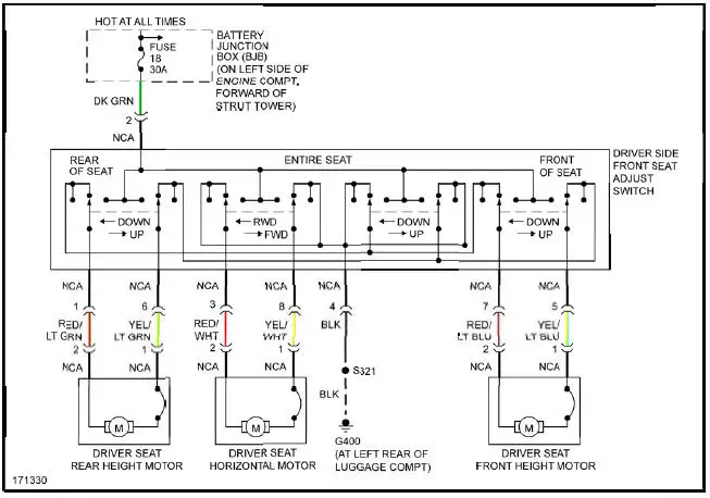
Fig. 38: Power Seat Circuit
POWER TOP/SUNROOF
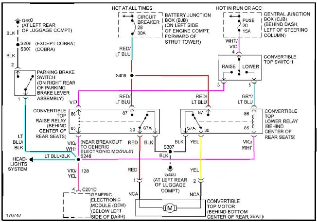
Fig. 39: Power Top/Sunroof Circuit
POWER WINDOWS
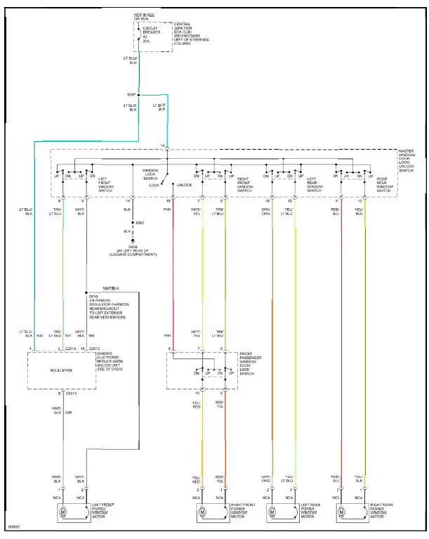
Fig. 40: Power Windows Circuit, Convertible
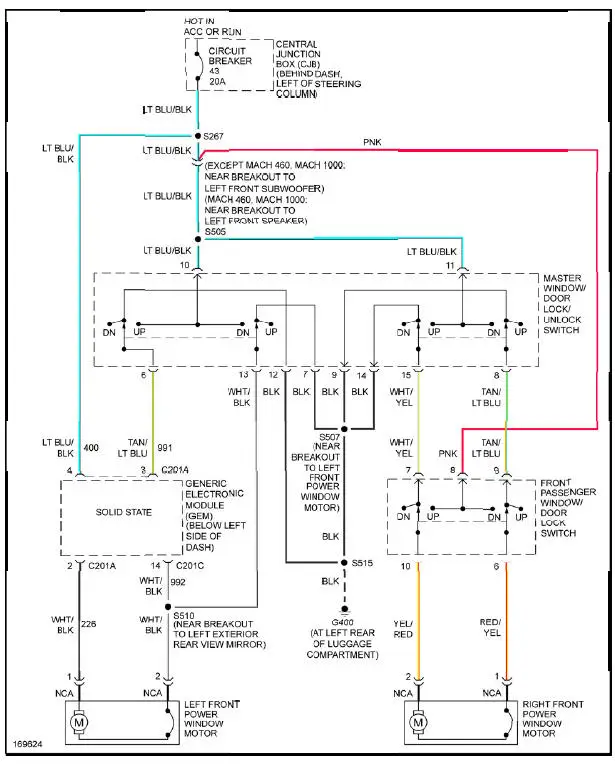
Fig. 41: Power Windows Circuit, Coupe
RADIO
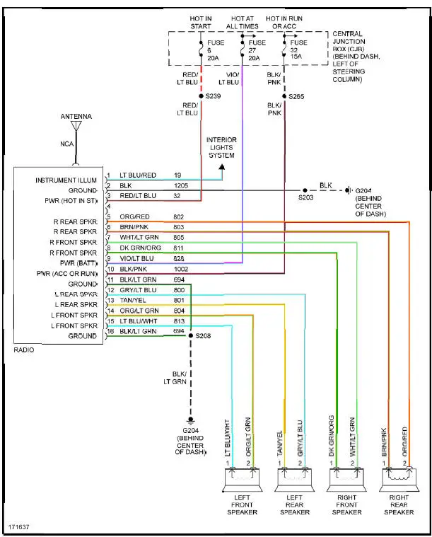
Fig. 42: Base Radio Circuit
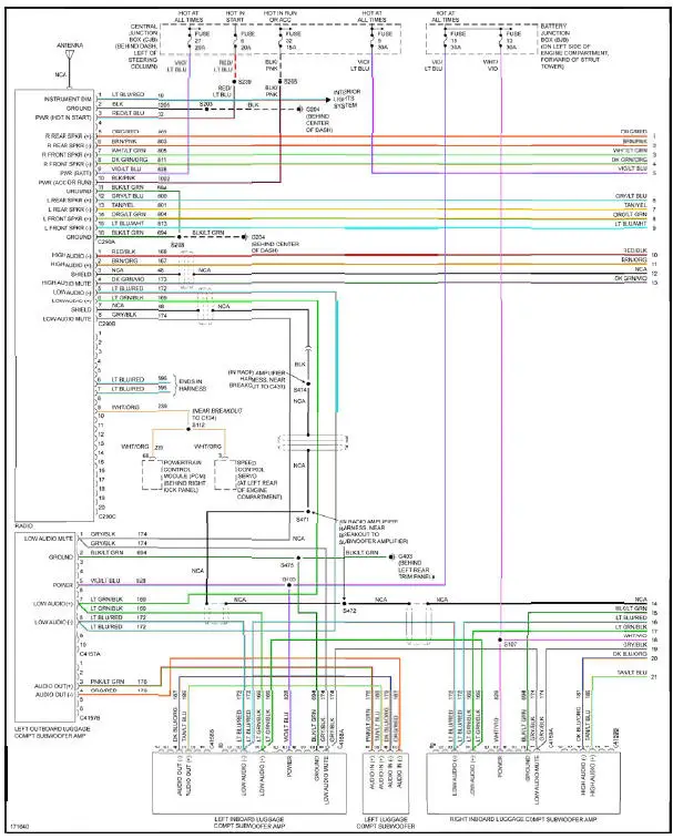
Fig. 43: Premium Sound Radio Circuit, Convertible W/ Mach 1000 Sound System (1 of 2)
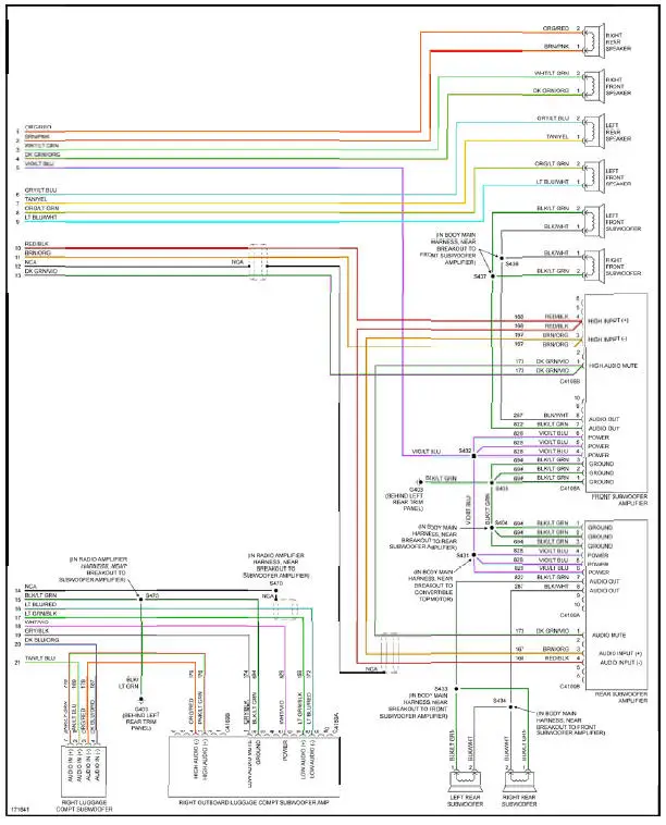
Fig. 44: Premium Sound Radio Circuit, Convertible W/ Mach 1000 Sound System (2 of 2)
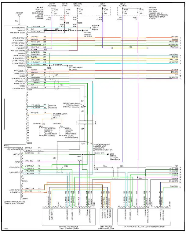
Fig. 45: Premium Sound Radio Circuit, Coupe W/ Mach 1000 Sound System (1 of 2)
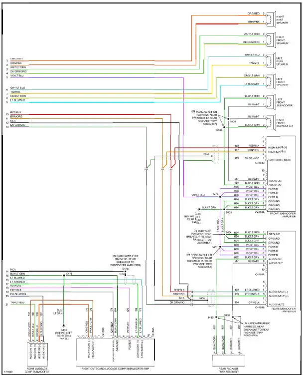
Fig. 46: Premium Sound Radio Circuit, Coupe W/ Mach 1000 Sound System (2 of 2)
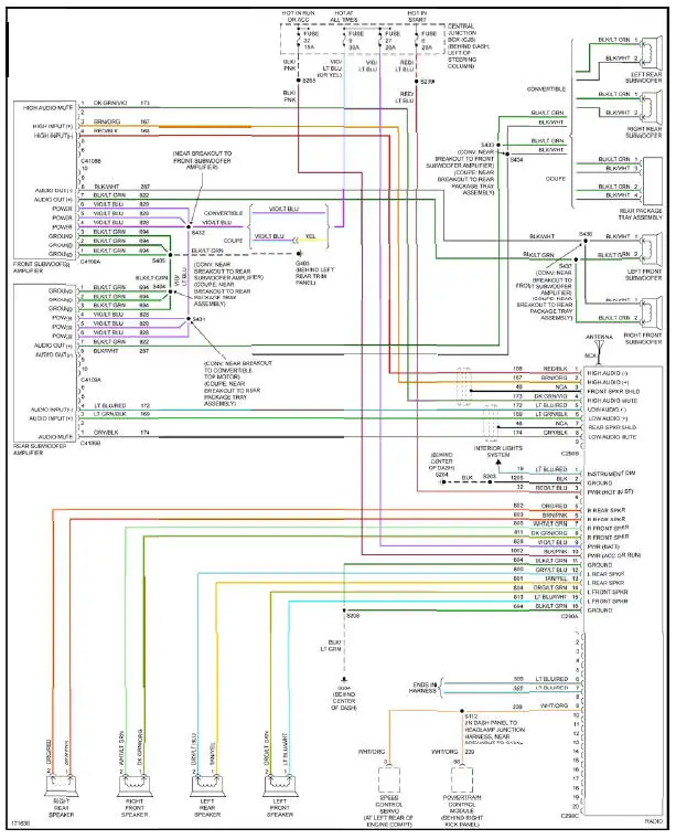
Fig. 47: Premium Sound Radio Circuit, W/ Mach 460 Sound System
SHIFT INTERLOCK
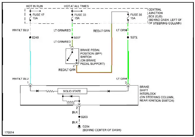
Fig. 48: Shift Interlock Circuit
STARTING/CHARGING
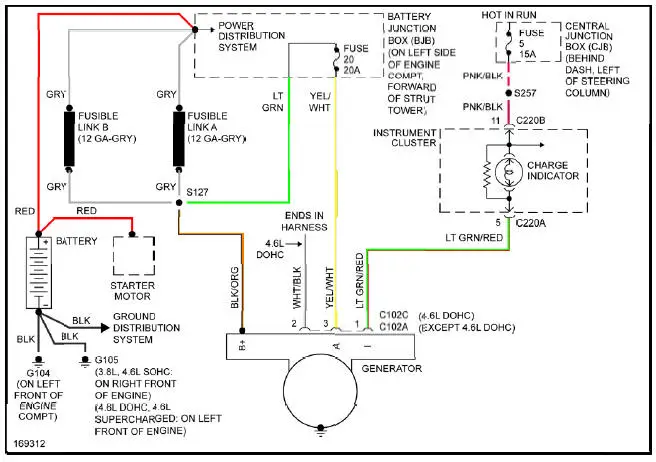
Fig. 49: Charging Circuit

Fig. 50: Starting Circuit
SUPPLEMENTAL RESTRAINTS

Fig. 51: Supplemental Restraints Circuit
TRANSMISSION
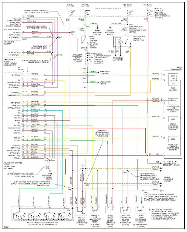
Fig. 52: A/T Circuit
TRUNK, TAILGATE, FUEL DOOR
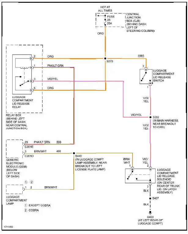
Fig. 53: Trunk, Tailgate, Fuel Door Circuit
WARNING SYSTEMS
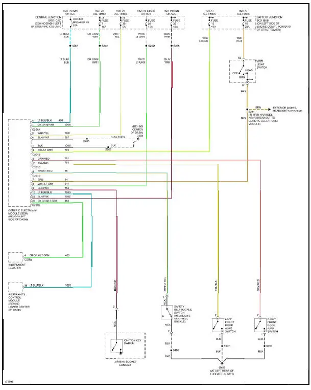
Fig. 54: Warning Systems Circuit
WIPER/WASHER
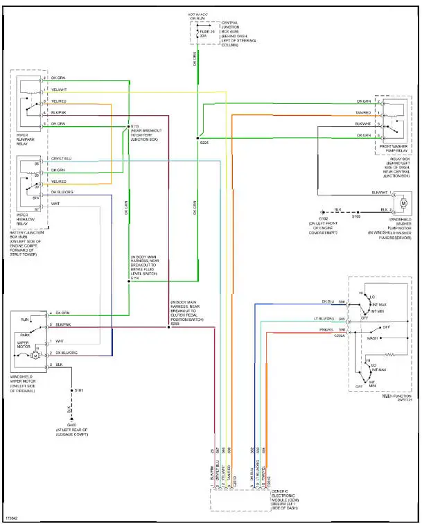
Fig. 55: Wiper/Washer Circuit
USING WIRING DIAGRAMS
For information on using these wiring diagrams, see USING SYSTEM WIRING DIAGRAMS article.
AIR CONDITIONING
3.8L
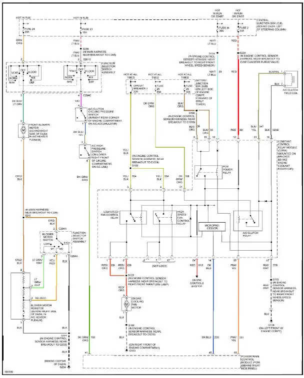
Fig. 1: 3.8L, Air Conditioning Circuit
4.6L
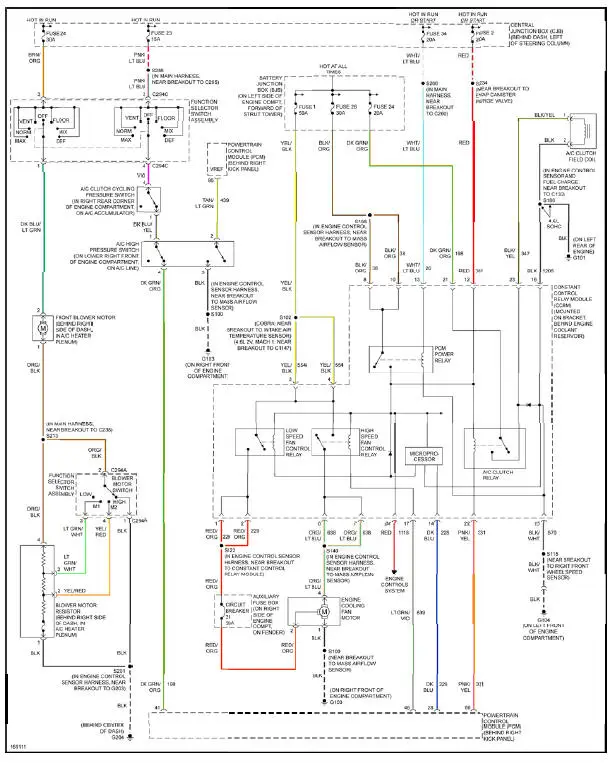
Fig. 2: 4.6L, Air Conditioning Circuit
ANTI-LOCK BRAKES
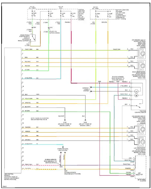
Fig. 3: Anti-lock Brakes Circuit
ANTI-THEFT

Fig. 4: Passive Anti-theft Circuit
BODY CONTROL MODULES

Fig. 5: Body Control Modules Circuit
COMPUTER DATA LINES
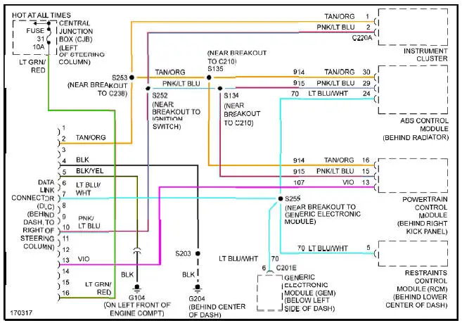
Fig. 6: Computer Data Lines Circuit
COOLING FAN
3.8L
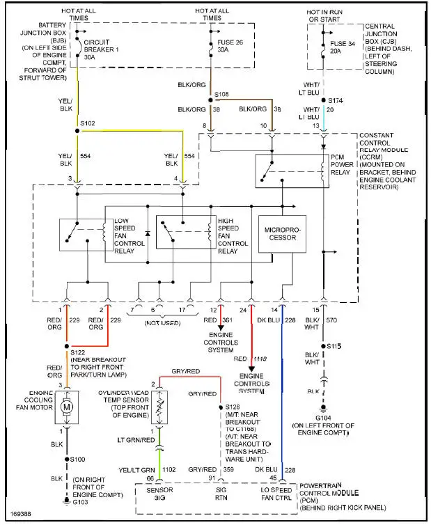
Fig. 7: 3.8L, Cooling Fan Circuit
4.6L
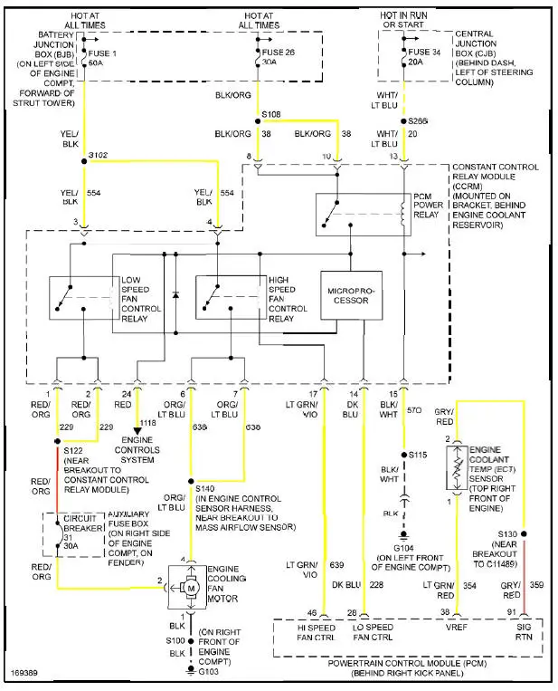
Fig. 8: 4.6L, Cooling Fan Circuit
CRUISE CONTROL
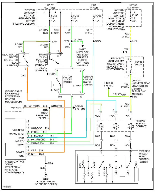
Fig. 9: Cruise Control Circuit
DEFOGGERS
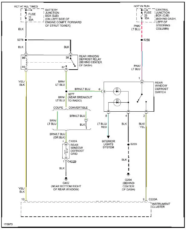
Fig. 10: Defoggers Circuit
ENGINE PERFORMANCE
3.8L
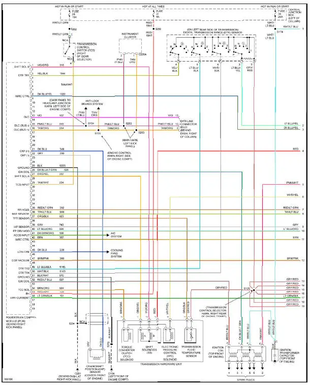
Fig. 11: 3.8L, Engine Performance Circuit (1 of 3)
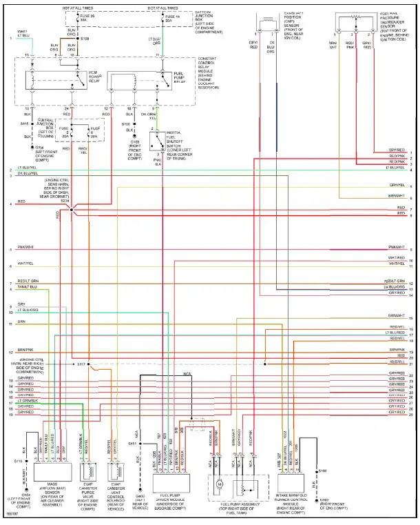
Fig. 12: 3.8L, Engine Performance Circuit (2 of 3)
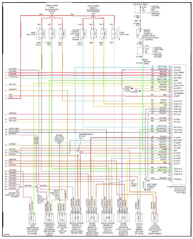
Fig. 13: 3.8L, Engine Performance Circuit (3 of 3)
4.6L DOHC

Fig. 14: 4.6L DOHC, Engine Performance Circuit (1 of 3)
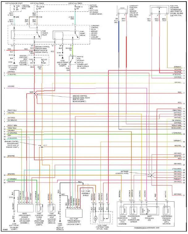
Fig. 15: 4.6L DOHC, Engine Performance Circuit (2 of 3)
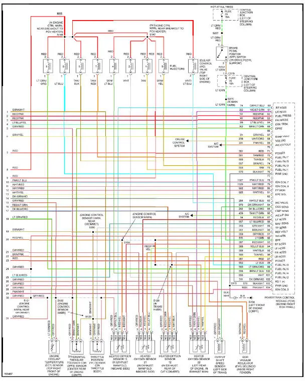
Fig. 16: 4.6L DOHC, Engine Performance Circuit (3 of 3)
4.6L SC
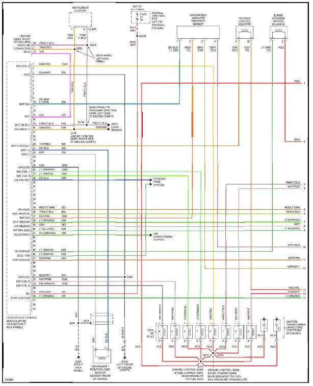
Fig. 17: 4.6L SC, Engine Performance Circuit (1 of 3)
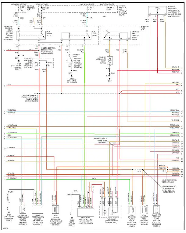
Fig. 18: 4.6L SC, Engine Performance Circuit (2 of 3)
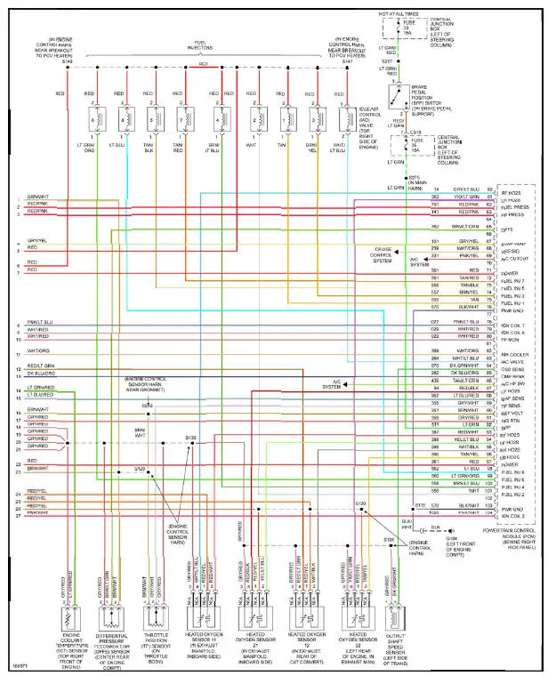
Fig. 19: 4.6L SC, Engine Performance Circuit (3 of 3)
4.6L SOHC
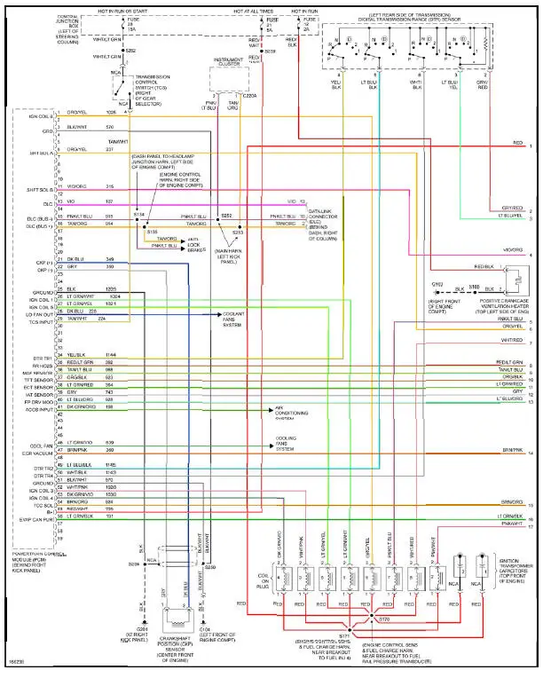
Fig. 20: 4.6L SOHC, Engine Performance Circuit (1 of 3)
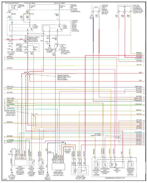
Fig. 21: 4.6L SOHC, Engine Performance Circuit (2 of 3)
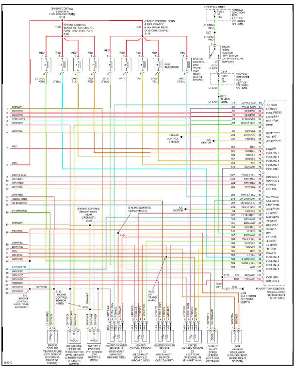
Fig. 22: 4.6L SOHC, Engine Performance Circuit (3 of 3)
EXTERIOR LIGHTS
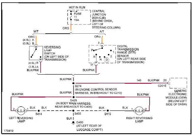
Fig. 23: Back-up Lamps Circuit
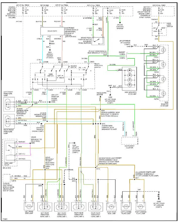
Fig. 24: Exterior Lamps Circuit
GROUND DISTRIBUTION
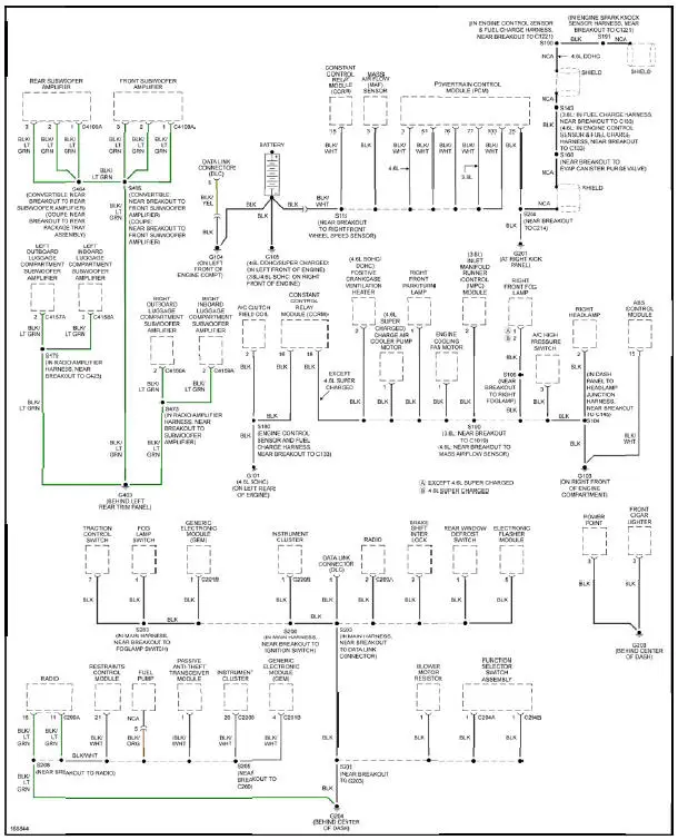
Fig. 25: Ground Distribution Circuit (1 of 2)

Fig. 26: Ground Distribution Circuit (2 of 2)
HEADLIGHTS
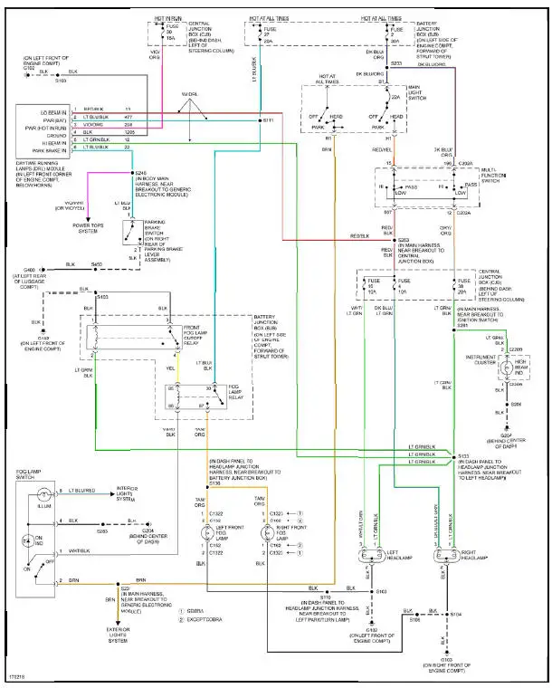
Fig. 27: Headlights Circuit
HORN

Fig. 28: Horn Circuit
INSTRUMENT CLUSTER
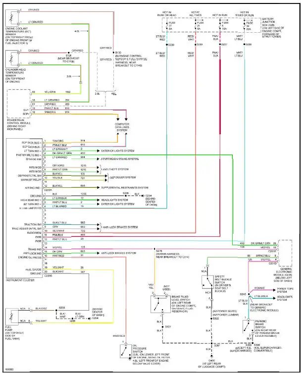
Fig. 29: Instrument Cluster Circuit
INTERIOR LIGHTS
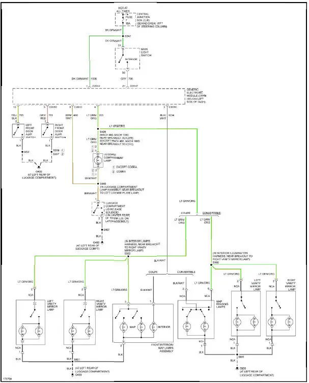
Fig. 30: Courtesy Lamps Circuit
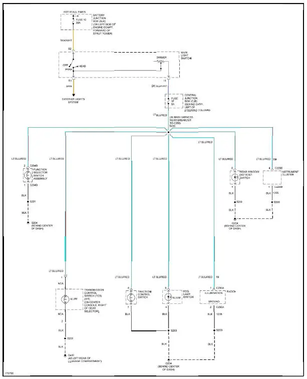
Fig. 31: Instrument Illumination Circuit
POWER DISTRIBUTION
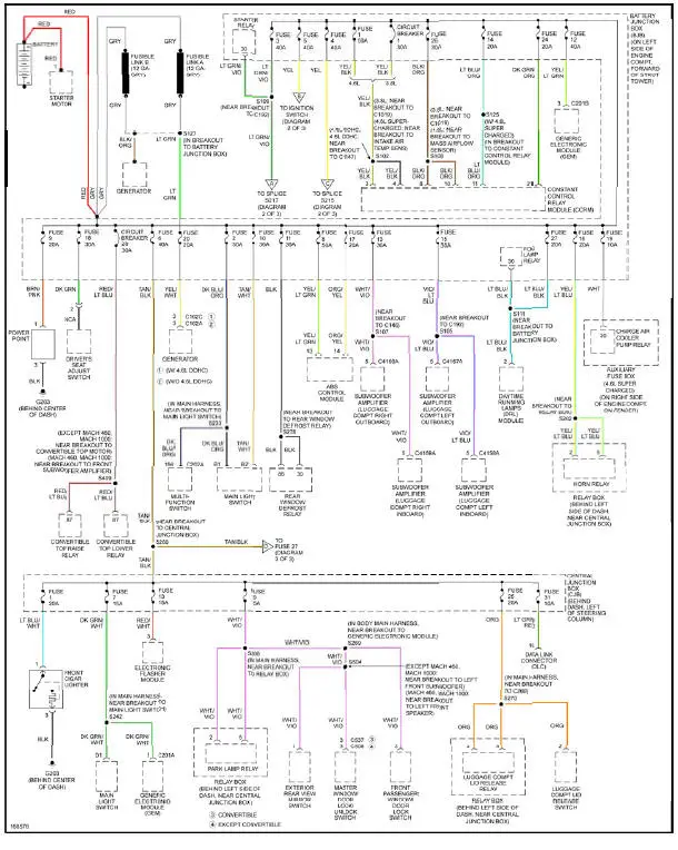
Fig. 32: Power Distribution Circuit (1 of 3)
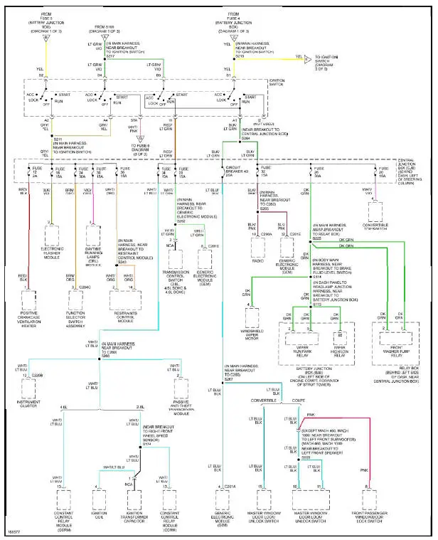
Fig. 33: Power Distribution Circuit (2 of 3)
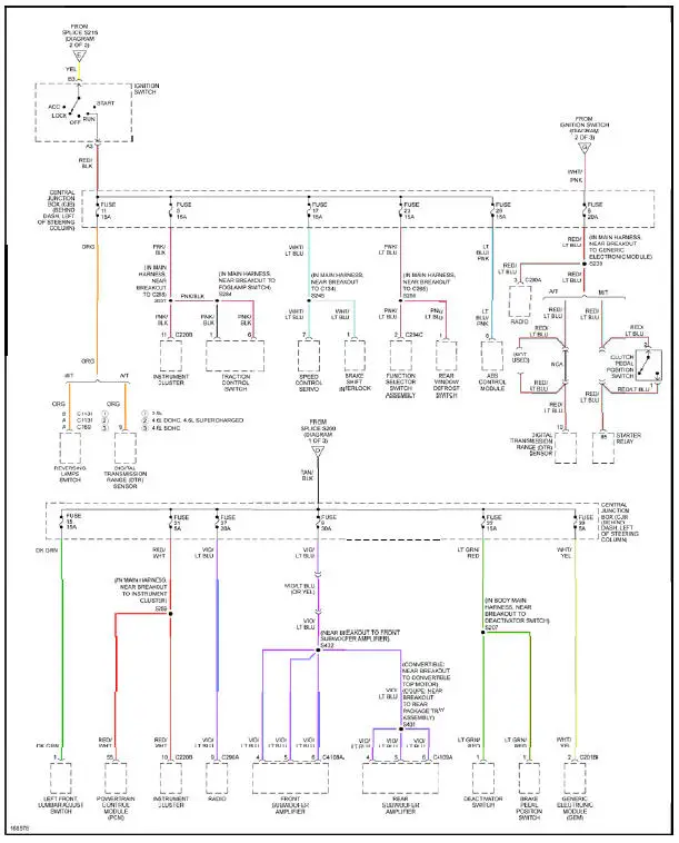
Fig. 34: Power Distribution Circuit (3 of 3)
POWER DOOR LOCKS
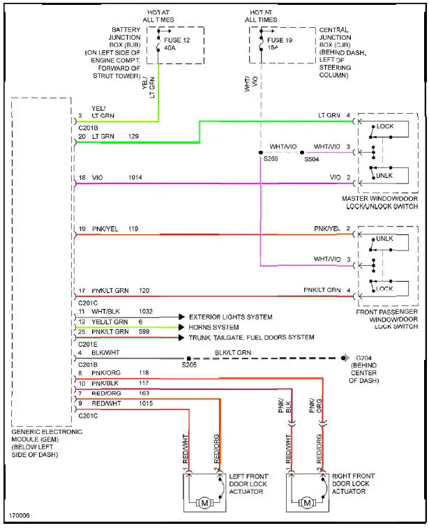
Fig. 35: Power Door Locks Circuit
POWER MIRRORS
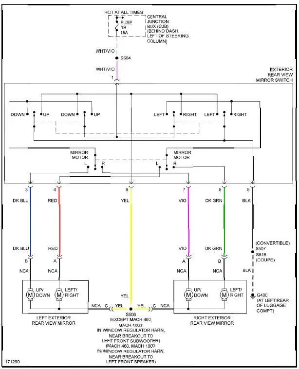
Fig. 36: Power Mirrors Circuit
POWER SEATS
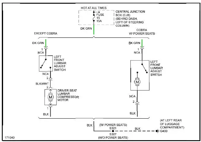
Fig. 37: Lumbar Circuit

Fig. 38: Power Seat Circuit
POWER TOP/SUNROOF
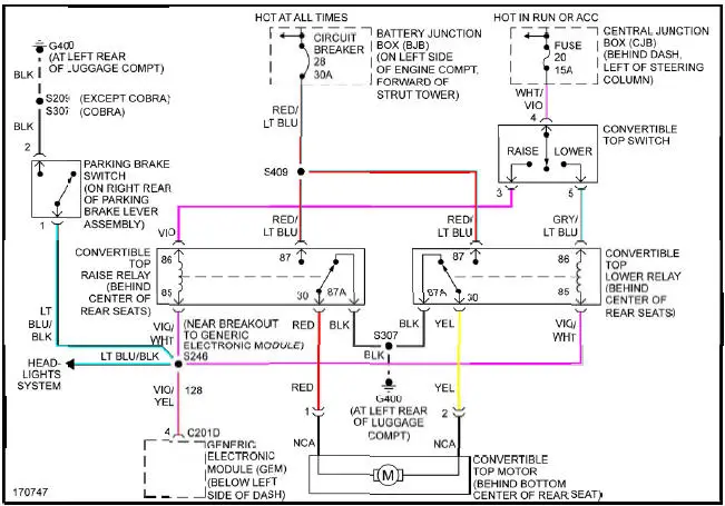
Fig. 39: Power Top/Sunroof Circuit
POWER WINDOWS
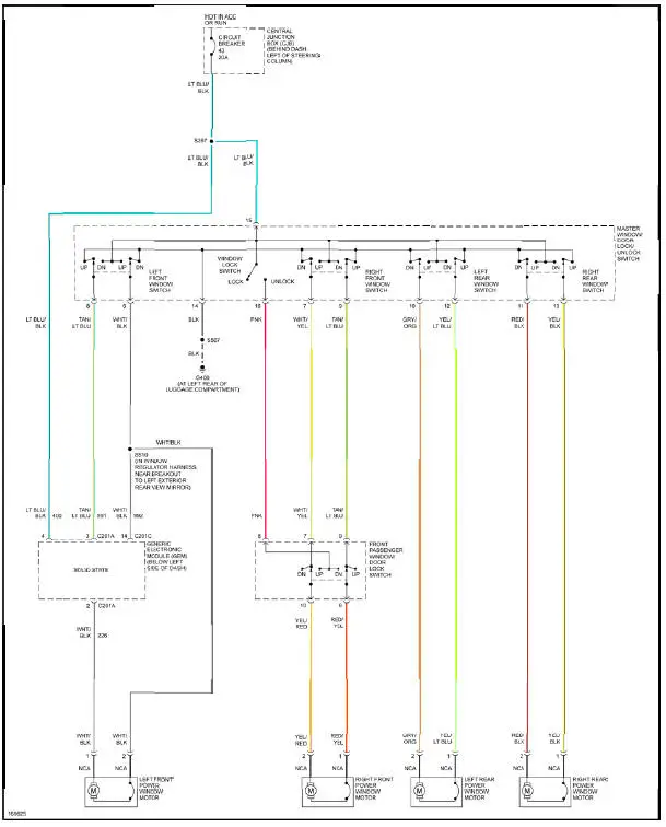
Fig. 40: Power Windows Circuit, Convertible
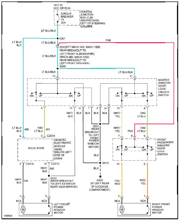
Fig. 41: Power Windows Circuit, Coupe
RADIO
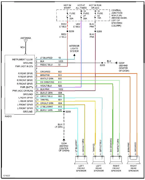
Fig. 42: Base Radio Circuit
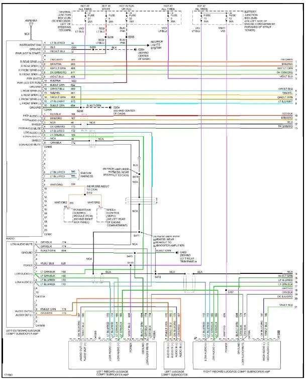
Fig. 43: Premium Sound Radio Circuit, Convertible W/ Mach 1000 Sound System (1 of 2)
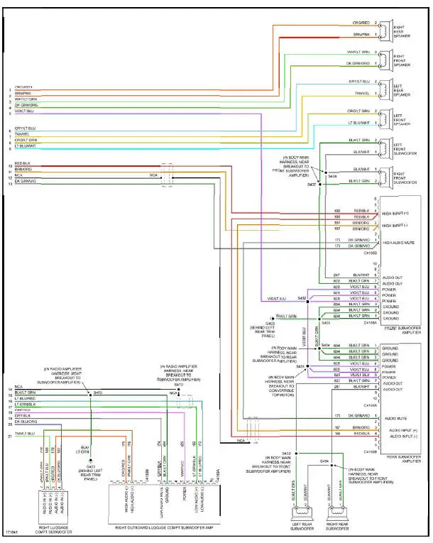
Fig. 44: Premium Sound Radio Circuit, Convertible W/ Mach 1000 Sound System (2 of 2)
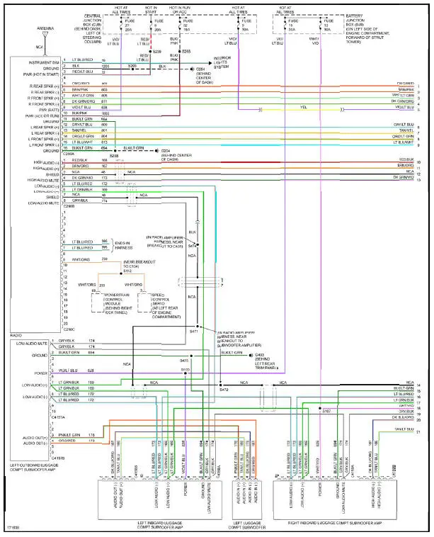
Fig. 45: Premium Sound Radio Circuit, Coupe W/ Mach 1000 Sound System (1 of 2)
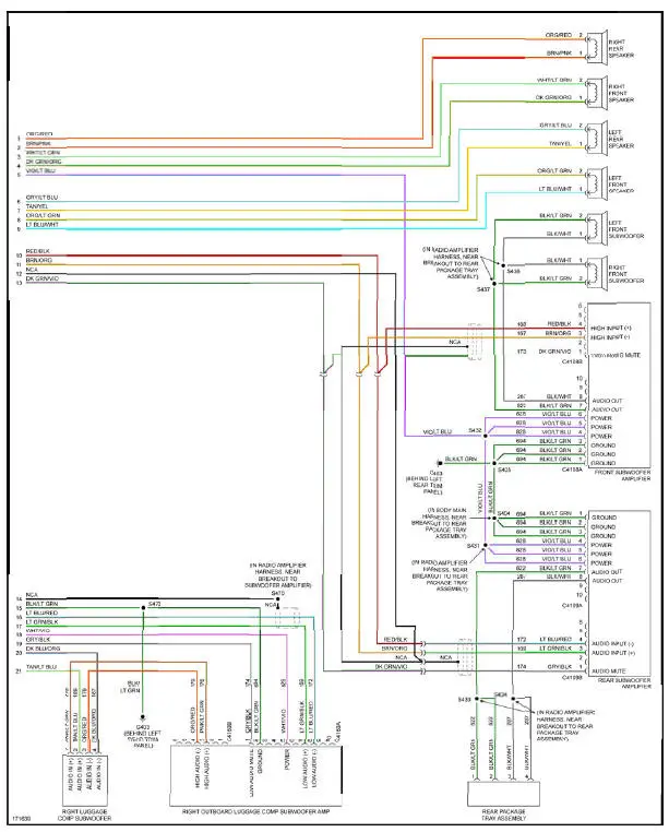
Fig. 46: Premium Sound Radio Circuit, Coupe W/ Mach 1000 Sound System (2 of 2)
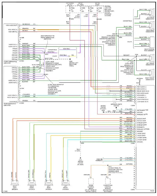
Fig. 47: Premium Sound Radio Circuit, W/ Mach 460 Sound System
SHIFT INTERLOCK

Fig. 48: Shift Interlock Circuit
STARTING/CHARGING

Fig. 49: Charging Circuit
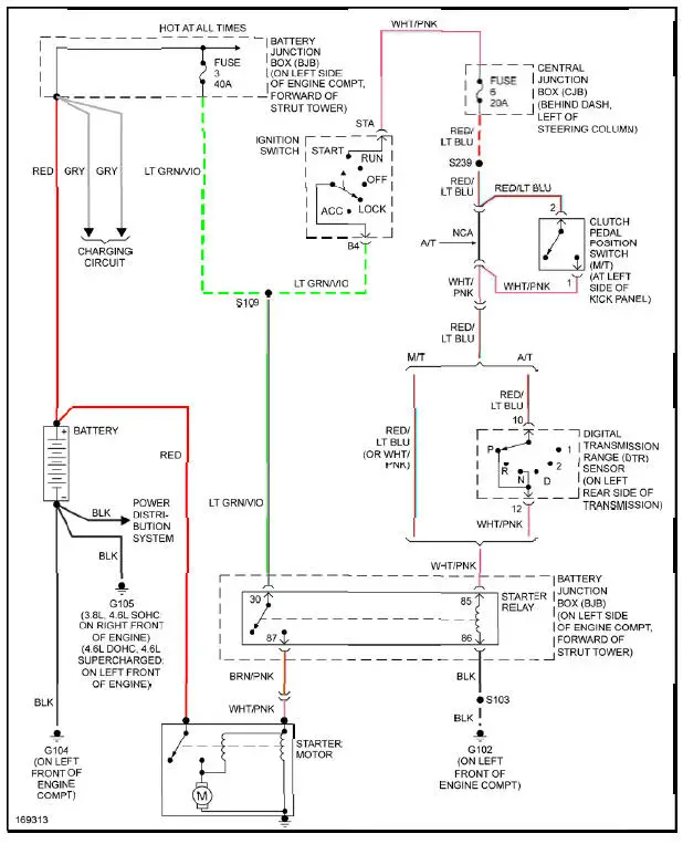
Fig. 50: Starting Circuit
SUPPLEMENTAL RESTRAINTS
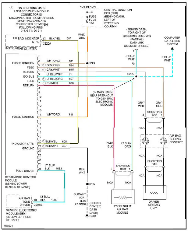
Fig. 51: Supplemental Restraints Circuit
TRANSMISSION
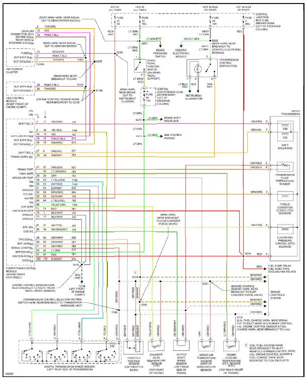
Fig. 52: A/T Circuit
TRUNK, TAILGATE, FUEL DOOR

Fig. 53: Trunk, Tailgate, Fuel Door Circuit
WARNING SYSTEMS
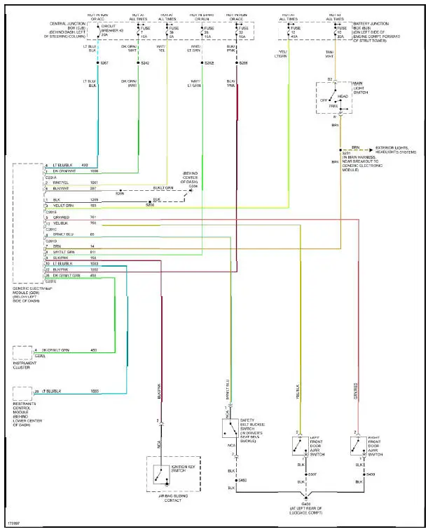
Fig. 54: Warning Systems Circuit
WIPER/WASHER
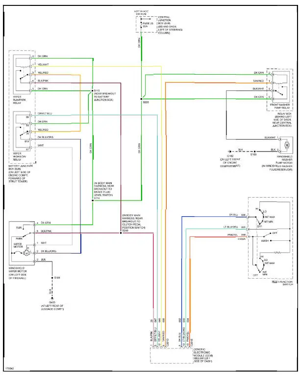
Fig. 55: Wiper/Washer Circuit
 Rear Subframe
Removal and Installation
CAUTION: Suspension fasteners are critical parts because they affect
performance of vital
components and systems and their failure can result in major service expense. A
new ...
Other materials:
Steering System Symptom Definitions
Drift/Pull
Pull is a tugging sensation, felt by the hands on the steering wheel, that
must be overcome to keep the
vehicle going straight.
Drift describes what a vehicle with this condition does with hands off the
steering wheel.
A vehicle-related drift/p ...
Removal
1. Disconnect the battery ground cable (14301).
2. Remove the air cleaner outlet tube (9B659).
3. Remove the radiator sight shield (8C291).
4. Remove the coolant recovery reservoir (8A080).
1. Disconnect the hose.
2. Remove the bolts.
3. Remo ...
Valve Stem to Valve Guide Clearance
Special Tool(s)
Dial Indicator Gauge with
Holding Fixture
100-002 (TOOL-4201-C) or
equivalent
Clearance Gauge, Valve Guide
303-004 (TOOL-6505-E) or
equivalent
NOTE: Valve stem diameter must be within specifications before
checkin ...
