Ford Mustang (1999-2004) Service Manual: Ignition Switch
Removal
1. Disconnect the battery ground cable.
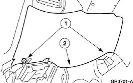
2. Remove the lower instrument panel steering column cover.
1. Remove the screws.
2. Remove the lower instrument panel steering column cover.
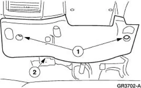
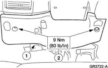
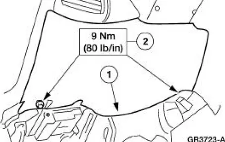
3. Remove the instrument panel reinforcement.
1. Remove the screws.
2. Remove the instrument panel reinforcement.
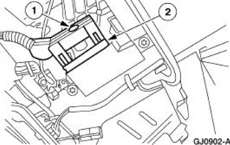
4. Disconnect the ignition switch electrical connector.
1. Loosen the bolt.
2. Disconnect the ignition switch electrical connector.
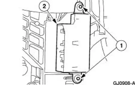
5. NOTE: Ignition switch should be in the OFF position.
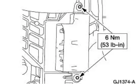
Remove the ignition switch.
1. Remove the screws.
2. Remove the ignition switch.
Installation
1. NOTE: When the battery is disconnected and reconnected, some abnormal drive symptoms may occur while the vehicle relearns its adaptive strategy. The vehicle may need to be driven 16 km (10 mi) or more to relearn the strategy.
To install, reverse the removal procedure.
 Multifunction Switch
Removal
1. Disconnect the battery ground cable.
2. Remove the ignition switch lock cylinder.
1. Insert the ignition key into the ignition switch lock cylinder and
turn to RUN position.
2. ...
 Key Release Button
Removal
1. Disconnect the battery ground cable.
2. Remove the ignition switch lock cylinder.
1. Insert the ignition key into the ignition switch lock cylinder and
turn to RUN position.
2. ...
Other materials:
Removal
1. Disconnect the battery negative cable.
2. Drain the engine cooling system.
3. Remove the RH exhaust manifold. For additional information, refer to Exhaust
Manifold RH in
this section.
4. Remove the lower intake manifold. For additional information, re ...
Main Control Valve Body
Special Tool(s)
Gauge, Transmission Solenoid
Connectors
307-426
Removal
1. Drain transmission fluid and remove the transmission fluid pan and
filter. For additional
information, refer to Fluid Pan, Gasket and Filter .
2. CAUTION: Do not ...
Caliper (DISASSEMBLY AND ASSEMBLY)
Disassembly
1. Remove the disc brake caliper (2B120). For additional information,
refer to Caliper in this
section.
2. Drain the remaining brake fluid from disc brake caliper.
3. Apply low air pressure to the fluid port in the disc brake caliper.
...
