Ford Mustang (1999-2004) Service Manual: Installation
CAUTION: Electronic modules are sensitive to static electrical charges. If exposed to these charges, damage may result.
1. NOTE: Two technicians are necessary to carry out this step.
Install the instrument panel.
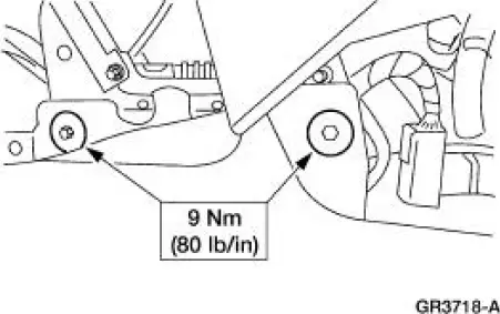
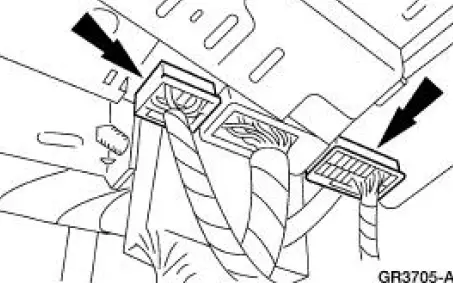
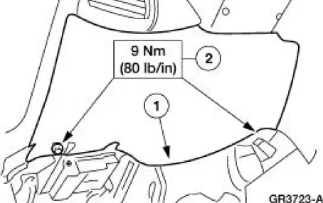
2. Install the upper instrument panel support bolts.
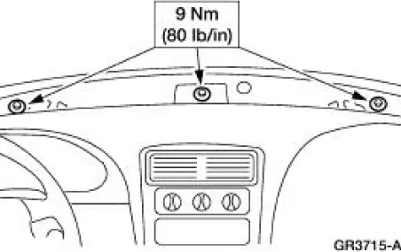
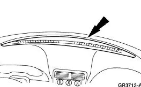
3. Install the instrument panel defroster grille.
4. Install the RH instrument panel support bolt.
5. Install the LH instrument panel support bolt and nut.
6. Install the four center instrument panel support bolts.
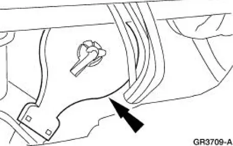
7. NOTE: This step is being carried out through the audio unit opening.
Install the temperature control cable to the blend door.
8. If equipped, connect the shifter assembly electrical connector.

9. Install the audio unit. For additional information, refer to Section.
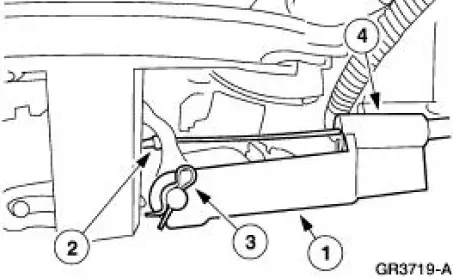
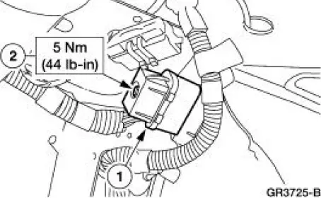
10. If equipped, connect the shift interlock assembly to the selector lever.
1. Position the shift interlock assembly.
2. Connect the shift interlock cable.
3. Install the R-clip.
4. Install the screw.
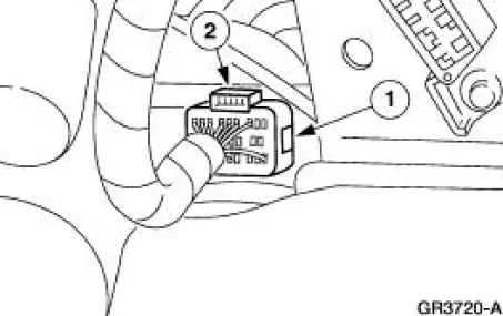
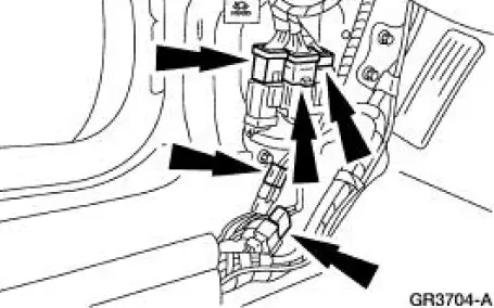
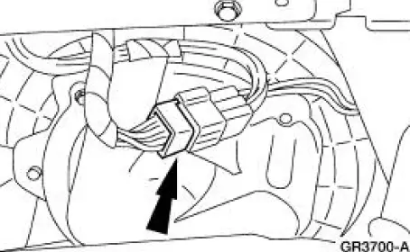
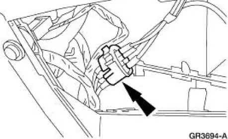
11. Connect the ECS module electrical connector.
1. Connect the ECS module electrical connector.
2. Engage the locking tab.
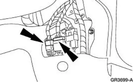
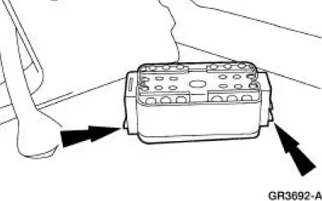
12. Connect the GEM electrical connectors.
13. Connect the LH main wiring harness electrical connectors.
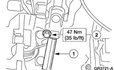
14. Connect the intermediate shaft to the steering column.
1. Connect the intermediate shaft to the steering column.
2. Install the pinch bolt.
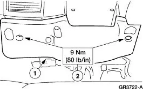
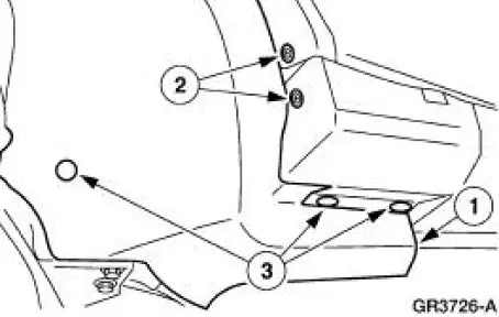
15. Install the instrument panel reinforcement.
1. Position the instrument panel reinforcement.
2. Install the screws.
16. Install the instrument panel steering column cover.
1. Position the instrument panel steering column cover.
2. Install the screws.
17. Connect climate control wiring harness connector.
18. Connect the RH main harness electrical connectors.
19. Install the LH and RH door weatherstrips.
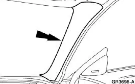
20. Install the LH and RH windshield side garnish mouldings.
- If equipped with a convertible top, install the pin-type retainers.
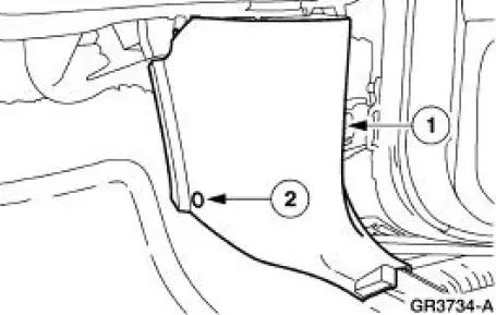
21. Install the LH and RH A-pillar lower trim panels.
1. Position the LH and RH A-pillar lower trim panels.
2. Install the pin-type retainers.
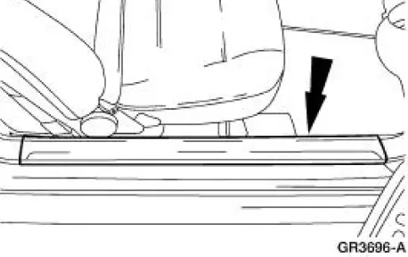
22. Install the LH and RH scuff plates.
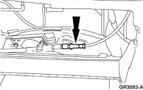
23. Open the glove compartment.
24. Connect the antenna in-line connector.
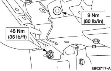
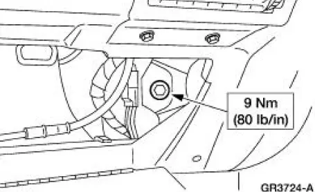
25. Install the upper RH instrument panel support bolt.
26. Connect the climate control vacuum harness connector.
27. Install the floor console. For additional information, refer to Floor Console in this section.
28. Remove the LH front wheel and tire assembly. For additional information, refer to Section.
29. Insert the bulkhead electrical connector into the dash panel.
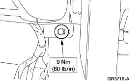
30. Connect the bulkhead electrical connector.
1. Connect the bulkhead electrical connector.
2. Tighten the bolt.
31. Install the LH front splash shield.
1. Position the LH front splash shield.
2. Install the screws.
3. Install the pin-type retainers.
32. Install the LH front wheel and tire assembly. For additional information, refer to Section.
33. Install the passenger air bag module. For additional information, refer to Section.
34. Install the driver air bag module. For additional information, refer to Section.
 Removal
CAUTION: Electronic modules are sensitive to static electrical
charges. If exposed to
these charges, damage may result.
1. Remove the driver air bag module. For additional information,
refer ...
 Instrument Panel - Center Finish Panel
Removal and Installation
All vehicles
1. Disconnect the battery ground cable. For additional information,
refer to Section.
Vehicles with automatic transmission
2. Place the selector lever ...
Other materials:
Tire Wear Chart
Wheel and tire NVH concerns are directly related to vehicle speed and are not
generally affected by
acceleration, coasting or decelerating. Also, out-of-balance wheel and tires can
vibrate at more than
one speed. A vibration that is affected by the engine ...
Connecting Rod - Bushing Diameter
1. Measure the inner diameter of the connecting rod bushing, if equipped.
Verify the diameter is
within specification.
Refer to the appropriate section in Group for the procedure.
If out of specification, install new components as necessary. Refer
...
Brake Disc Machining
Special Tool(s)
Gauge, Clutch Housing
308-021 (T75L-4201-A)
Dial Indicator Gauge with
Holding Fixture
100-002 (TOOL-4201-C) or
equivalent
Material
Item
Specification
Metal Surface Cleaner
F4AZ-19A536-RA or equiv ...
