Ford Mustang (1999-2004) Service Manual: Pinpoint Test D: LFC 15/DTC B 1887- Driver Air Bag Circuit Shorted to Ground
Normal Operation
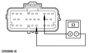
The restraints control module (RCM) checks for driver air bag circuit shorts to ground by monitoring the voltage of circuits 614 (GY/OG) and 615 (GY/WH) at pins 3 and 4. If the RCM detects a short to ground on either of these pins, it will store a diagnostic trouble code (DTC) B1887 in memory and flash a lamp fault code (LFC) 15 (or higher priority code if one exists) on the air bag indicator.
Possible Causes
A driver air bag circuit short to ground can be caused by:
- a short to ground on circuit 614 (GY/OG).
- a short to ground on circuit 615 (GY/WH).
- a short to ground on the clockspring (14A664).
- a short to ground on the driver air bag module.
- an RCM internal concern.
PINPOINT TEST D: LFC 15/DTC B1887 - DRIVER AIR BAG CIRCUIT SHORTED TO GROUND
| Test Step | Result / Action to Take |
| D1 CHECK FOR A HARD OR INTERMITTENT DTC | Yes This is a hard fault. The fault condition is still present. This fault cannot be cleared until it is corrected and the DTC is no longer retrieved during the on-demand self test. GO to D2 . No This is an intermittent fault. The fault condition is not present at this time. GO to D5 . |
|
|
| D2 CHECK THE DRIVER AIR BAG MODULE | Yes GO to D3 . No INSTALL a new driver air bag module. GO to D6 |
| WARNING: If the supplemental restraint system
(SRS) is
being serviced, the system must be deactivated and restraint
system diagnostic tools must be installed. Refer to Air Bag
Supplemental Restraint System (SRS) in this section. The air bag restraint system diagnostic tools must be removed and the air bag modules reconnected when the system is reactivated to avoid non-deployment in a collision, resulting in possible personal injury. NOTE: Diagnostics or repairs are not to be performed on a seat equipped with a seat side air bag with the seat in the vehicle. Prior to attempting to diagnose or repair a seat concern when equipped with a seat side air bag, the seat must be removed from the vehicle and the restraint system diagnostic tools must be installed in the seat side air bag electrical connectors. The restraint system diagnostic tools must be removed prior to operating the vehicle over the road. NOTE: After diagnosing or repairing an SRS, the restraint system diagnostic tools must be removed before operating the vehicle over the road. NOTE: After diagnosing or repairing a seat system, the restraint system diagnostic tools must be removed before operating the vehicle over the road. NOTE: The SRS must be fully operational and free of faults before releasing the vehicle to the customer.
|
|
| D3 CHECK THE DRIVER AIR BAG MODULE CIRCUIT | Yes GO to D4 . No INSTALL a new RCM. GO to D6 . |
|
|
| D4 CHECK THE DRIVER AIR BAG MODULE WIRING AND THE CLOCKSPRING | Yes REPAIR as necessary. GO to D6 . No GO to D6 . |
|
|
| D5 CHECK FOR AN INTERMITTENT FAULT | Yes CHECK for causes of intermittent short to ground on circuit 614 (GY/OG), circuit 615 (GY/WH), and the clockspring assembly. Attempt to recreate the hard fault by flexing the wire harness and cycling the ignition key frequently. REPAIR any intermittent concerns found. GO to D6 . No GO to D6 . |
|
|
| D6 CHECK FOR ADDITIONAL DTCs | Yes Do not clear any DTCs until all DTCs have been resolved. GO to the Restraints Control Module (RCM) Diagnostic Trouble Code (DTC) Priority Table in this section for pinpoint test direction. No RECONNECT the system. REACTIVATE the system. PROVE OUT the system. REFER to Air Bag Supplemental Restraint System (SRS) in this section. CLEAR all DTCs. |
|
 Pinpoint Test C: LFC 29/DTC C1414 - Incorrect Vehicle Identification Code
Normal Operation
The restraints control module (RCM) monitors the electrical state of pins
10, 13 and 14 to determine if
it is installed on the correct vehicle. If the RCM detects an incorrect
c ...
 Pinpoint Test E: LFC 15/DTC B1916 - Driver Air Bag Circuit Shorted to
Battery or Ignition
Pinpoint Test E: LFC 15/DTC B1916 - Driver Air Bag Circuit Shorted to
Battery or Ignition
Normal Operation
The restraints control module (RCM) checks for driver air bag circuit
shorts to battery or ignition by
monitoring the voltage of circuit 614 (GY/OG) and 615 (GY/WH) at pins 3 and ...
Other materials:
Generator and Regulator
General Specifications
Torque Specifications
Generator
The charging system consists of the:
generator (GEN)
internal voltage regulator
The generator has an internal voltage regulator that is not installed
separately. The generator and
v ...
Removal
1. Remove the roller followers. For additional information, refer to Roller
Followers in this section.
2. Remove the spark plugs. For additional information, refer to Section .
3. Position the piston of the cylinder being serviced at the bottom of the
stro ...
Principles of Operation
There are four main principles involved with the basic theory of
operation:
heat transfer
latent heat of vaporization
relative humidity
effects of pressure
Heat Transfer
If two substances of different temperature are placed near each other,
t ...
