Ford Mustang (1999-2004) Service Manual: Control Components (Description and Operation)
Manual A/C
The climate control system heats or cools the vehicle interior depending on the function selector position and the temperature selected. Function selector position determines heating or cooling and air distribution. The temperature blend control setting determines air temperature.
The manual climate control components are used to:
- select air inlet source (outside or recirculated).
- select blower motor speed.
- select discharge air temperature (temperature blend).
- select discharge air location (defrost, panel, floor).
- select A/C compressor clutch operation.
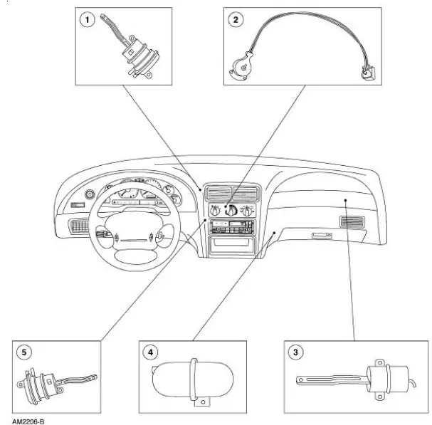
Component Locations
Control System Inputs
Climate Control Assembly
The climate control assembly has three system controls:
- The blower motor switch controls blower motor speed by adding or bypassing resistors in the heater blower motor resistor.
- The temperature selection is accomplished with a manually-controlled blend door actuator that controls positioning of the temperature blend door. Movement of the control knob (18519) from COOL (blue) to WARM (red) causes a corresponding movement on the air temperature control door and determines the temperature that the system will maintain.
- The A/C heater function selector switch combines a vacuum selector valve for direct control of the vacuum control motors and electrical input to the instrument control module.
Control System Outputs
Blower Motor Switch Resistor
The heater blower motor switch resistor has the following features:
- The assembly is located on the passenger side of the plenum assembly behind the glove compartment (06010).
- Three resistance elements are mounted on the resistor board to provide four A/C blower motor speeds.
- Depending on the heater blower motor switch position, series resistance is added or bypassed in the A/C blower motor circuit to decrease or increase A/C blower motor speed.
- An overheating protective device (thermal limiter) will open the resistor coil circuit when the temperature reaches 105-110C (221-230F), interrupting the blower motor operation in all speeds except HI.
- The thermal limiter cannot be reset and is not serviceable.
Control Actuators
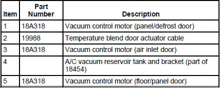
Temperature Control Cable
The temperature control cable (19988) has the following features:
- The cable assembly has a constant tension (pull-pull) dual cable design.
- The pull-pull design allows for constant smooth communication between the temperature control knob and the air temperature blend door.
- The control cable can only be installed as an assembly.
Vacuum Control Motors
The vacuum control motors (18A318) control the position of the doors directing the air flow to the different outlets. There are two types of vacuum control motors used in this system:
- Single-diaphragm for air inlet and windshield defroster door operations.
- Double-diaphragm for air damper door operations.
Single-diaphragm motors have two positions:
- Shaft extended with no vacuum applied.
- Shaft retracted with vacuum applied.
Double-diaphragm motors have three positions:
- Shaft extended with no vacuum applied to either port.
- Shaft halfway retracted with vacuum applied to only one port.
- Shaft fully retracted with vacuum applied to both ports.

 Control Assembly
Special Tool(s)
Remover, Heater Control
Cable Retainer
412-088 (T94P-18532-A)
...
Other materials:
Driver and passenger airbags
WARNING: Never place your arm or any objects over an airbag
module. Placing your arm over a deploying airbag can result in
serious arm fractures or other injuries. Objects placed on or over the
airbag inflation area may cause those objects to be propelled by t ...
Component Tests
Drive Belt Noise/Flutter
Drive belt chirp occurs due to pulley misalignment or excessive pulley runout.
It can be the result of a
damaged pulley or an incorrectly aligned pulley.
To correct, determine the area where the noise comes from. Check each of the
p ...
Electronic Engine Controls (Description and Operation)
The electronic engine controls consist of the following:
powertrain control module (PCM)
throttle position (TP) sensor
idle air control (IAC) valve
engine coolant temperature (ECT) sensor
cylinder head temperature sensor
camshaft position ...
