Ford Mustang (1999-2004) Service Manual: Brake Disc Machining
Special Tool(s)
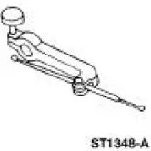 |
Gauge, Clutch Housing 308-021 (T75L-4201-A) |
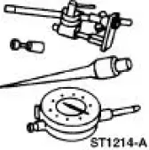 |
Dial Indicator Gauge with Holding Fixture 100-002 (TOOL-4201-C) or equivalent |
Material
| Item | Specification |
| Metal Surface Cleaner F4AZ-19A536-RA or equivalent | WSE-M5B392- A |
| High Temperature Nickel Anti- Seize Lubricant F6AZ-9L494-AA or equivalent | ESE-M12A4-A |
WARNING: The electrical power to the air suspension system must be shut off prior to hoisting, jacking or towing an air suspension vehicle. This can be accomplished by turning off the air suspension switch. Failure to do so can result in unexpected inflation or deflation of the air springs, which can result in shifting of the vehicle during these operations.
CAUTION: Do not install brake discs that are less than the minimum thickness specified.
Do not machine a brake disc below the minimum thickness specification.
1. Check wheel bearing end-play and correct as necessary.
2. NOTE: Begin at the front of the vehicle unless the vibration has been isolated to the rear.
Remove the tire and wheel assembly.
3. Remove the brake caliper and the brake caliper anchor plate. Refer to the appropriate section in Group 206 for the procedure.
4. Inspect the brake linings. Install new brake linings if below specification. For additional information, refer to the appropriate brake section.
5. Measure and record the brake disc thickness. Install a new brake disc if the thickness after machining will be at or below specification. The specification is molded into the brake disc.
- Do not machine a new brake disc.
6. For vehicles with a two-piece hub and brake disc assembly:
- Match-mark before disassembly.
- Remove the brake disc.
- Clean the hub and brake disc mounting surfaces with metal surface cleaner.
- Using a die grinder with a mild abrasive (Scotch Brite type), remove any rust or corrosion from the hub and brake disc mounting surfaces.
- Align the match-marks and reinstall the brake disc on the hub.
7. CAUTION: Do not use a bench lathe to machine brake discs.
NOTE: The depth of cut must be between 0.10 and 0.20 mm (0.004 and 0.008 inch). Lighter cuts will cause heat and wear. Heavier cuts will cause poor brake disc surface finish.
Using an on-car brake lathe, machine the brake discs. Follow the manufacturer's instructions.
After machining, make sure the brake disc still meets the thickness specification.
8. Using the special tools, verify that the brake disc lateral runout is now within specification. For additional information.
9. Remove the special tool hub adapter.
10. Remove any remaining metal chips from the machining operation.
11. For vehicles with a two-piece hub and brake disc assembly:
- Remove the brake disc from the hub.
- Remove any remaining metal chips from hub and brake disc mounting surfaces and from the ABS sensor.
- Apply a liberal amount of lubricant to the hub flange, pilot area and to the brake disc-tohub mounting surface.
- Using the match marks, mount the brake disc on the hub.
12. Install the brake caliper anchor plate and the brake caliper.
13. Install the tire and wheel assembly.
14. Test the system for normal operation.
 Tire Wear Chart
Wheel and tire NVH concerns are directly related to vehicle speed and are not
generally affected by
acceleration, coasting or decelerating. Also, out-of-balance wheel and tires can
vibrate at more ...
 Powertrain/Drivetrain Mount Neutralizing
WARNING: The electrical power to the air suspension system must be shut
off prior to
hoisting, jacking or towing an air suspension vehicle. This can be accomplished
by turning off
the air suspension ...
Other materials:
Hydraulic Control Unit
Removal
1. Disconnect the battery ground cable(14301).
2. Disconnect the anti-lock-brake control module electrical connector.
3. NOTE: The 4 wheel anti-lock brake system (4WABS) with traction
control is shown , the
4WABS without traction control system is ...
Front Seat Cushion
Disassembly and Assembly
All vehicles
1. Remove the seat track. For additional information, refer to Seat Track
in this section.
2. Remove the seat backrest. For additional information, refer to Front Seat
Backrest in this
section.
Vehicles with powe ...
Installation
1. NOTE: Inspect the spring insulators for wear or damage. Install new
spring insulators if
necessary.
Make sure the spring insulators are correctly installed on the springs.
2. Install the springs.
1. Position the springs.
2. Raise the subframe using ...
