Ford Mustang (1999-2004) Service Manual: Fog Lamps
Refer to Wiring Diagrams Cell 86 , Fog Lamps for schematic and connector information.
Special Tool(s)
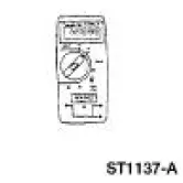 |
73 III Automotive Meter or equivalent 105-R0057 |
Principles of Operation
The fog lamps will only illuminate when the low beam or parking lamps are illuminated. Voltage from the parking lamp circuit is used to activate the fog lamp relay when the fog lamp switch is ON. Voltage from the high beam headlamp circuit will activate the fog lamp interrupt relay. When the fog lamp interrupt relay is active, the ground path is removed from the fog lamp relay, turning off the fog lamps.
Inspection and Verification
1. Verify the customer concern by operating the fog lamps.
2. Visually inspect for the following obvious signs of mechanical and electrical damage.
Visual Inspection Chart
| Mechanical |
Electrical |
|
|
3. If the concern is not visually evident, determine the symptom and proceed to Symptom Chart.
Symptom Chart
| Condition | Possible Sources | Action |
|
|
|
|
|
|
|
|
|
Pinpoint Tests
PINPOINT TEST O: THE FOG LAMPS ARE INOPERATIVE
| Test Step | Result / Action to Take |
| O1 CHECK THE PARK LAMPS | Yes Turn off the headlamp switch. GO to O2 . No GO to Pinpoint Test L . |
|
|
| O2 CHECK THE FOG LAMP RELAYS | Yes GO to O3 . No INSTALL new relay(s). TEST the system for normal operation |
|
|
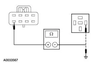
| O3 CHECK THE CIRCUIT 12 (LG/BK) | Yes GO to O4 . No REPAIR the circuit. TEST the system for normal operation. |
|
|
| O4 CHECK CIRCUIT 275 (YE) | Yes GO to O5 . No REPAIR the circuit. TEST the system for normal operation |
|
|
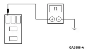
| O5 CHECK CIRCUIT 477 (LB/BK) FOR OPEN | Yes GO to O6 . No REPAIR the circuit. TEST the system for normal operation. |
|
|
| O6 CHECK CIRCUIT 188 (WH/BK) | Yes GO to O7 . No REPAIR the circuit. TEST the system for normal operation. |
|
|
| O7 CHECK CIRCUIT 1205 (BK) | Yes GO to O8 . No REPAIR the circuit. TEST the system for normal operation. |
|
|
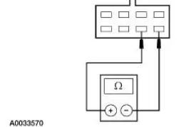
| O8 CHECK THE FOG LAMP SWITCH | Yes REPAIR Circuit 478 (TN/OG). TEST the system for normal operation. No INSTALL a new fog lamp switch. TEST the system for normal operation. |
|
PINPOINT TEST P: THE INDIVIDUAL FOG LAMP IS INOPERATIVE
| Test Step | Result / Action to Take |
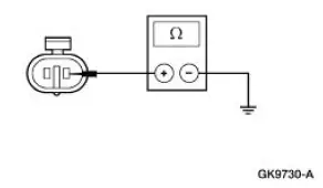
| P1 CHECK THE GROUND TO THE FOG LAMP | Yes REPAIR Circuit 478 (TN/OG) for open. TEST the system for normal operation. No REPAIR Circuit 1205 (BK). TEST the system for normal operation. |
|
PINPOINT TEST Q: THE FOG LAMPS ARE ON CONTINUOUSLY
| Test Step | Result / Action to Take |
| Q1 CHECK THE FOG LAMP RELAY | Yes GO to Q2 . No REPAIR Circuit 478 (TN/OG). TEST the system for normal operation. |
|
|
| Q2 CHECK FOG LAMP RELAY | Yes RECONNECT the fog lamp relay. GO to Q3 . No INSTALL a new fog lamp relay. TEST the system for normal operation. |
|
|
| Q3 CHECK FOG LAMP SWITCH | Yes INSTALL a new fog lamp switch. TEST the system for normal operation. No REPAIR Circuit 188 (WH/BK) for short. TEST the system for normal operation. |
|
 Parking, Rear and License Lamps
Refer to Wiring Diagrams Cell 92 , Exterior for schematic and connector
information.
Special Tool(s)
73 III Automotive Meter or
equivalent
105-R0057
Inspection and Verification
1 ...
 Reversing Lamps
Refer to Wiring Diagrams Cell 93 , Backup Lamps for schematic and
connector information.
Special Tool(s)
73III Automotive Meter or
equivalent
105-R0057
Inspection and Verification
...
Other materials:
Engine Mount RH
Special Tool(s)
Lifting Bracket, Engine
303-D088 (D93P-6001-A2)
Support Bar, Engine
303-290-A
Removal
1. Install the special tool.
2. Install the special tools.
3. Remove the starter. For additional information, refer to Secti ...
Window Glass - Quarter
Removal
1. Remove the quarter trim panel. For additional information, refer
to Section.
2. Remove the roof side trim moulding. For additional information, refer
to Section.
3. Remove the exterior quarter glass weatherstrip.
4. Remove the nuts.
...
Door Alignment
NOTE: The door should be adjusted for even and parallel fit with the
body opening and surrounding
panels as well as making sure that the anti-chuck pin is not binding on
convertible models.
1. Mark the position of the front door hinges to the front ...
