Ford Mustang (1999-2004) Service Manual: Headlamps
Refer to Wiring Diagrams Cell 85 , Headlamps for schematic and connector information.
Special Tool(s)
 |
73III Automotive Meter or equivalent 105-R0057 |
Inspection and Verification
1. Verify the customer concern by operating the headlamps.
2. Visually inspect for the following obvious signs of mechanical and electrical damage.
Visual Inspection Chart
| Mechanical | Electrical |
|
|
3. If the concern is not visually evident, determine the symptom and proceed to Symptom Chart.
Symptom Chart
| Condition | Possible Sources | Action |
|
|
|
|
|
|
|
|
|
|
|
|
|
|
|
|
|
|
|
|
|
Pinpoint Tests
PINPOINT TEST A: BOTH HEADLAMPS ARE INOPERATIVE
| Test Step | Result / Action to Take |
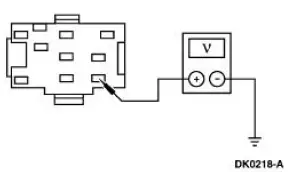
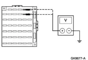
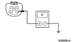
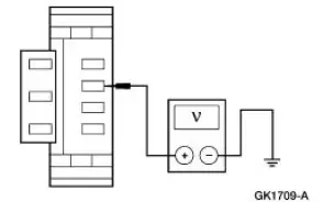
| A1 CHECK THE VOLTAGE TO THE HEADLAMP SWITCH | Yes GO to A2 . No REPAIR the circuit. TEST the system for normal operation. |
|
|
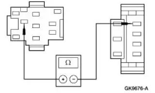
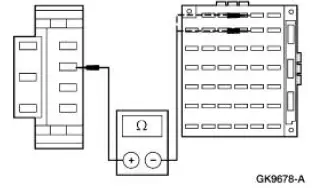
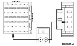
| A2 CHECK CIRCUIT 15 (RD/YE) FOR OPEN | Yes RECONNECT headlamp switch C205. GO to A3 . No REPAIR the circuit. TEST the system for normal operation. |
|
|
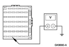
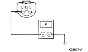
| A3 CHECK THE VOLTAGE TO THE MULTIFUNCTION SWITCH | Yes INSTALL a new multifunction switch; REFER to Section. TEST the system for normal operation. No INSTALL a new headlamp switch; REFER to Lamp Switch-Headlamp in this section. TEST the system for normal operation. |
|
PINPOINT TEST B: THE LOW BEAMS ARE INOPERATIVE
| Test Step | Result / Action to Take |
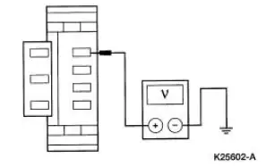
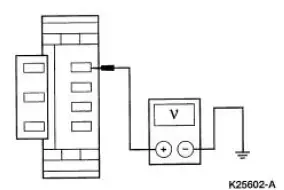
| B1 CHECK THE VOLTAGE TO CJB FUSE 4 (7.5A) AND CJB FUSE 10 (7.5A) | Yes Go To Pinpoint Test D . No GO to B2 . |
|
|
| B2 CHECK CIRCUIT 13 (RD/BK) FOR OPEN | Yes INSTALL a new multifunction switch; REFER to Section. TEST the system for normal operation. No REPAIR the circuit. TEST the system for normal operation. |
|
PINPOINT TEST C: THE HIGH BEAMS ARE INOPERATIVE
| Test Step | Result / Action to Take |
| C1 CHECK THE CIRCUIT 12 (LG/BK) | Yes RECONNECT the LH headlamp (13008). GO to C2 . No REPAIR the circuit. TEST the system for normal operation. |
|
|
| C2 CHECK THE VOLTAGE TO CJB FUSE 38 (20A) | Yes Go To Pinpoint Test E . No GO to C3 . |
|
|
| C3 CHECK CIRCUIT 632 (GY/OG) FOR OPEN | Yes INSTALL a new multifunction switch; REFER to Section. TEST the system for normal operation. No REPAIR the circuit. TEST the system for normal operation |
|
PINPOINT TEST D: ONE LOW BEAM HEADLAMP IS INOPERATIVE
| Test Step | Result / Action to Take |
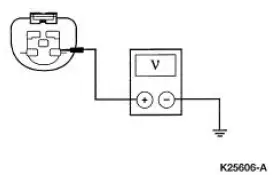
| D1 CHECK THE VOLTAGE TO THE INOPERATIVE HEADLAMP BULB | Yes INSTALL a new headlamp bulb; REFER to Bulb-Headlamp in this section. TEST the system for normal operation. No REPAIR the circuit. TEST the system for normal operation. |
|
PINPOINT TEST E: ONE HIGH BEAM HEADLAMP IS INOPERATIVE
| Test Step | Result / Action to Take |
| E1 CHECK THE VOLTAGE TO THE INOPERATIVE HEADLAMP BULB | Yes INSTALL a new headlamp bulb; REFER to Bulb- Headlamp in this section. TEST the system for normal operation. No REPAIR the circuit. TEST the system for normal operation. |
|
PINPOINT TEST F: THE HEADLAMPS ARE ON CONTINUOUSLY
| Test Step | Result / Action to Take |
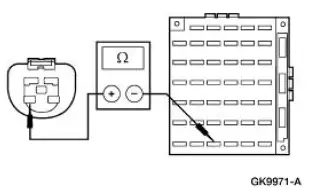
| F1 CHECK THE HEADLAMP SWITCH | Yes GO to F2 . No INSTALL a new headlamp switch; REFER to Lamp Switch-Headlamp in this section. TEST the system for normal operation. |
|
|
| F2 CHECK THE MULTIFUNCTION SWITCH | Yes GO to F4 . No GO to F3 . |
|
|
| F3 CHECK CIRCUIT 15 (RD/YE) FOR SHORT TO POWER | Yes REPAIR the circuit. TEST the system for normal operation. No INSTALL a new multifunction switch; REFER to Section 211- 05 . TEST the system for normal operation. |
|
|
| F4 CHECK CIRCUIT 13 (RD/BK) FOR SHORT TO POWER | Yes REPAIR the circuit. TEST the system for normal operation. No GO to F5 . |
|
|
| F5 CHECK CIRCUIT 1056 (DB, LG) FOR VOLTAGE | Yes REPAIR Circuit 1056 (DB/LG). TEST the system for normal operations. No REPAIR Circuit 1055 (WH/LG). TEST the system for normal operations. |
|
 Exterior Lighting
Torque Specifications
Exterior Lighting
The exterior lighting system consists of the following components:
headlamps (13008)
parking lamps
rear lamps (13404)
high mounted stoplamp
...
 Stoplamps
Refer to Wiring Diagrams Cell 90 , Turn/Stop/Hazard Lamps for
schematic and connector information.
Special Tool(s)
73III Automotive Meter or
equivalent
105-R0057
Inspection and Ve ...
Other materials:
Lumbar Control Switch
Removal and Installation
All vehicles
1. Remove the front seat. For additional information, refer to Seat-Front
Power in this section.
Vehicles with standard power lumbar
2. Pull to remove the lumbar control switch (14C715).
3. Disconnect the power lum ...
Sprockets
1. WARNING: To avoid the possibility of personal injury or damage
to the vehicle, do
not operate the engine with the hood open until the fan blade has been
examined for
possible cracks and separation.
NOTE: Specifications show the expected minimum or ma ...
Cruise Control
PRINCIPLES OF OPERATION
Cruise control lets you maintain a set speed without keeping your foot
on the accelerator pedal.
USING CRUISE CONTROL
WARNING: Do not use cruise control in heavy traffic, on
winding roads or when the road surface is slippery. This coul ...
