Ford Mustang (1999-2004) Service Manual: Actuator Cable - Speed Control
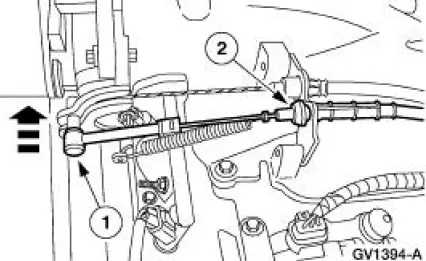
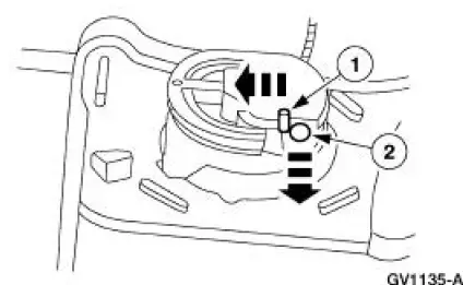
1. Remove the speed control actuator cable end from the throttle body.
1. Lift the speed control cable from the throttle nailhead.
2. Release the speed control cable from the throttle bracket.
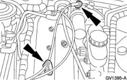
2. Remove the speed control cable from the retaining clips.
3. Remove the LH front wheel and tire assembly. For additional information, refer to Section.
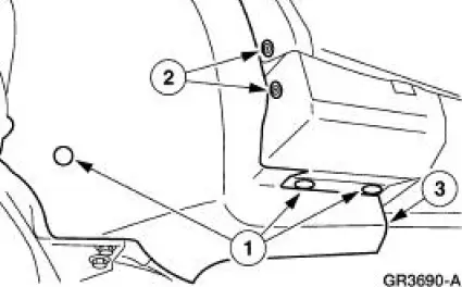
4. Position aside the LH front splash shield.
1. Remove the pin-type retainers.
2. Remove the screws.
3. Position aside the LH front splash shield.
5. Depress the locking tab and rotate the speed control actuator cable cap to remove.
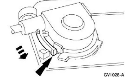
6. Disconnect the speed control actuator cable from the speed control servo pulley.
1. Gently push in the retaining spring.
2. Disconnect the speed control cable slug from the speed control servo pulley.
Installation
1. To install, reverse the removal procedure.
 Pinpoint Tests
PINPOINT TEST A: THE SPEED CONTROL IS INOPERATIVE
Test Step
Result / Action to Take
A1 CHECK THE SPEED CONTROL SERVO VOLTAGE AND
GROUND
YesGO to A3 .
No
GO to A2 .
Ke ...
 Actuator Cable - Speed Control-Cobra
1. Remove the speed control actuator cable end from the throttle body.
1. Lift the speed control cable from the throttle nailhead.
2. Release the speed control cable from the throttle bracket.
...
Other materials:
Shield
Removal
1. Remove the brake disc (1125). For additional information, refer to
Disc in this section.
2. Remove the brake disc shield (2K004).
1. Drill out three brake disc shield rivets.
2. Remove the brake disc shield.
Installation
1. I ...
Gauges And Warning Devices
Refer to Wiring Diagrams Cell 59 , Generic Electronic Module for
schematic and connector
information.
Refer to Wiring Diagrams Cell 60 , Instrument Cluster for schematic and
connector information.
Refer to Wiring Diagrams Cell 66 , Warning Chime ...
Differential Pressure Feedback Exhaust Gas Recirculation
(EGR) System
Removal and Installation
1. NOTE: The 4.6L (2V) is shown. The 4.6L (4V) and 3.8L are
similar.
NOTE: Bolts may be used in place of nuts on some applications.
Remove the differential pressure feedback EGR.
1. Disconnect the connector.
2. Remove the ...
