Ford Mustang (1999-2004) Service Manual: Air Distribution
NOTE: The air distribution system of this vehicle cannot be equipped with a cabin air filter.
There are two sources of air available to the air distribution system:
- outside air
- recirculated air
Recirculated air is only used during MAX A/C.
Air distribution within the vehicle is determined by the function selector switch position. Airflow control doors are used to direct airflow within the air plenum chamber. Vacuum control motors (18A318) are used to position these airflow control doors. Refer to Section for a description and operation of each of the system functions.
The air distribution system is designed to provide airflow from the defrost nozzle when no vacuum is applied to any of the vacuum control motors. This is done to prevent a situation where defrost cannot be obtained due to a system vacuum leak.
Air enters the passenger compartment from the:
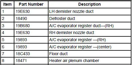
- instrument panel A/C register (19893).
- heater outlet floor duct (18C433).
- windshield defroster hose nozzle (18490).
- side window demisters.
Passenger compartment air is exhausted from the vehicle through open windows or body air vents.
Instrument Panel Registers
There are A/C registers on the left and right sides of the instrument panel and in the center instrument panel finish panel.
The LH and RH A/C registers are only serviceable as assemblies.
The center A/C registers are not serviceable as assemblies. The registers are installed with the instrument panel center finish panel assembly.
Component Locations
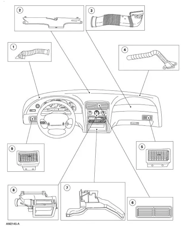

 Air Distribution and Filtering
Torque Specifications
...
 Register - LH
Removal
1. Remove the instrument panel steering column cover bolts.
2. Unsnap and remove the instrument panel steering column cover.
3. Remove the bolts and the steering column reinforcement.
4. ...
Other materials:
Knock
Knock, which can occur on all driving phases, has several causes including
damaged teeth or gearset.
In most cases, one of the following conditions will occur:
1. A gear tooth damaged on the drive side is a common cause of the knock.
This can usually be
cor ...
Installation
All vehicles
CAUTION: After installing the urethane installed windshield,
the vehicle should not be
driven until the urethane adhesive has cured. The curing time at
temperatures above 13C (55
F) and relative humidity above 50% is 12-24 hours (Refer ...
Ignition Coil-On-Plug
Material
Item
Specification
Silicone Brake Caliper Grease
and Dielectric Compound
D7AZ-19A331-A or equivalent
ESE-M1C171-
A
Removal and Installation
1. Disconnect the battery ground cable. For additional information, refer
to Section ...
