Ford Mustang (1999-2004) Service Manual: Apply Components
There are eight apply components used to drive or hold the planetary gearset components.
Band-Overdrive
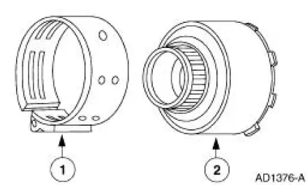
1. The overdrive band holds the reverse clutch drum stationary in fourth gear and manual
2. This action causes the reverse sun gear to be held in these ranges.
Band-Low and Reverse

The low and reverse band holds the pinion carrier in reverse. The reverse band also applies in manual 1 position to provide engine braking.
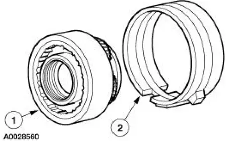
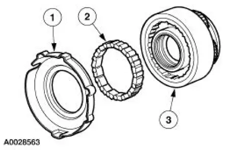
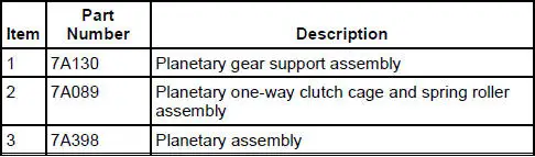
Clutch-Intermediate
Intermediate Clutch Disassembled View
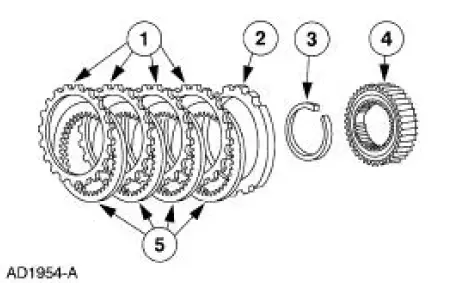
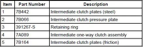
The intermediate clutch works with the intermediate one-way clutch to hold the reverse sun gear stationary in second gear. The intermediate clutch remains applied in third and fourth gears, but does not transmit power.
Clutch-Forward
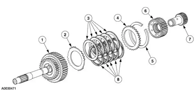
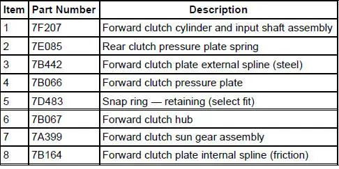
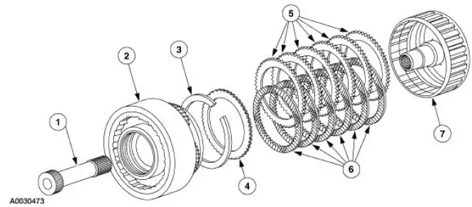
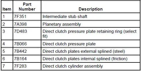
The direct clutch couples the input shaft to the planet carrier through the stub shaft in third and fourth gears.
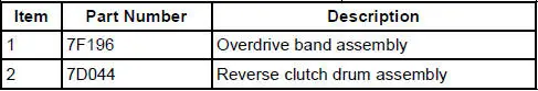
Clutch-Reverse
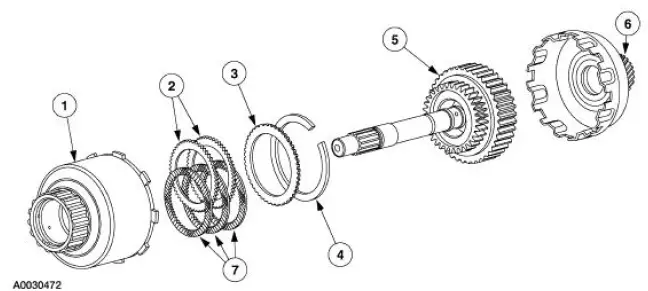

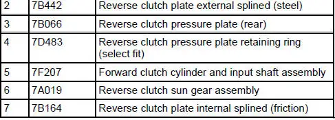
The reverse clutch couples the input shaft to the reverse sun gear, applied in reverse range only.
One-Way Clutch-Planetary (Low)
The planetary (low) one-way clutch is a roller clutch that holds the planetary gearset in first gear, (D) and D ranges. During automatic coasting downshifts into first gear ((D) and D ranges), the planetary one-way clutch freewheels so there is no engine braking.
One-Way Clutch-Intermediate
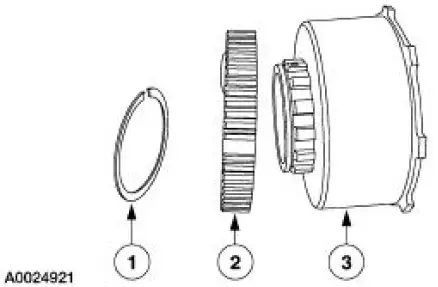
The intermediate one-way clutch works with the intermediate friction clutch to hold the reverse clutch drum and reverse sun gear stationary in second gear during acceleration. The intermediate one-way clutch freewheels in third gear and during coasting in second gear, (D) and D ranges.
 Geartrain
Power is transmitted from the torque converter to the Ravigneaux
geartrain components through the
input shaft and forward clutch cylinder.
The geartrain contains a Ravigneaux planetary set ...
 Hydraulic System
Fluid Pump
The transmission uses a gerotor-type design front pump support and gear. The
pump provides the
volume of fluid needed to charge the torque converter, main control asse ...
Other materials:
Rear Drive Axle/Differential - Ford 7.5-Inch Ring Gear
General Specifications
a: In-vehicle repair refill capacities are determined by filling the rear axle
with the specified lubricant to
6.4-14.3-mm (1/4-9/16-in) below the bottom of the fill hole.
Torque Specifications
...
Cleaning the engine
Engines are more efficient when they are clean because grease and dirt
buildup keep the engine warmer than normal.
When washing:
• Take care when using a power washer to clean the engine. The
high-pressure fluid could penetrate the sealed parts and cause
da ...
Convertible Top (Description and Operation)
Rear Window Glass Assembly
The convertible top assembly is equipped with a rear window glass
assembly. The rear window glass
assembly is permanently attached to the folding top rear window curtain
and cannot be opened. The
rear window gl ...
