Ford Mustang (1999-2004) Service Manual: Assembly
1. Install the locking lever cam and pin.
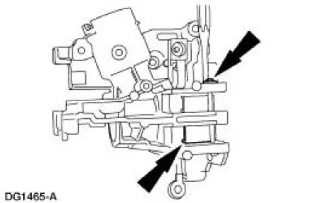
2. Install the lock actuator lever and pin.
3. Install the lock actuator lever return spring.
4. Install the ignition lock cylinder lockout lever.
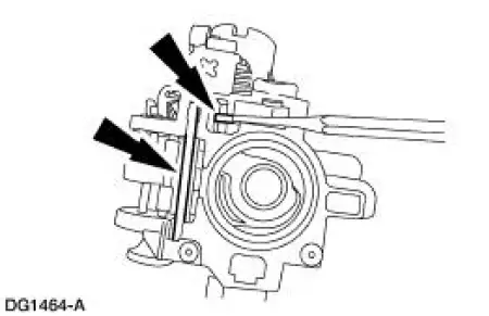
5. NOTE: The lock lever with two teeth is installed on the left-hand side.
If necessary, install the springs and lock levers.
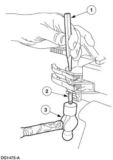
1. Install the spring and lever on the left-hand side. Use a pin punch to hold the compressed spring in position.
2. Install the spring and lever on the right-hand side. Use the pivot pin to hold the compressed spring in position.
3. Tap the pin through the levers, pushing out the pin punch, until flush with the housing.
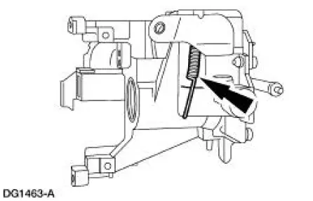
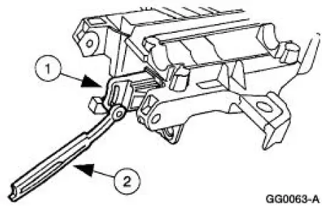
6. Install the lock lever actuators.
1. Lubricate the lock lever actuator with Ignition Lock Grease F0AZ-19584-A or equivalent meeting Ford specification ESA-M1C232-A.
2. Install the lock lever actuators.
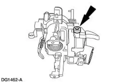
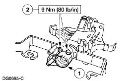
7. Install the lower bearing retainer.
1. Position the lower bearing retainer.
2. Install the three bolts.
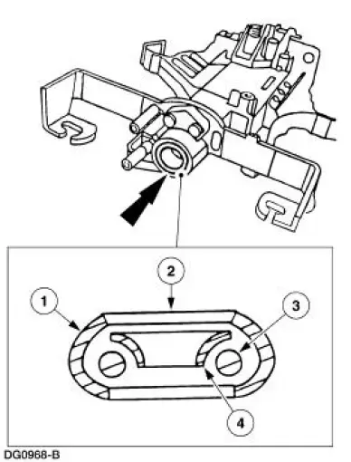
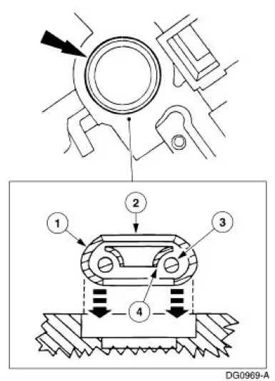
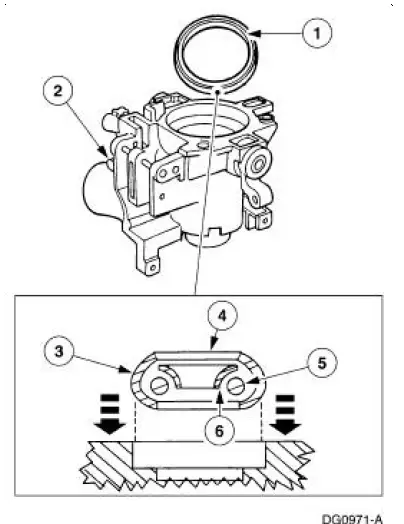
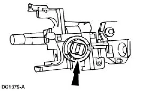
8. NOTE: The "UP" position of the bearing must be facing forward.
Install the lower bearing and sleeve.
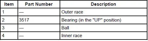
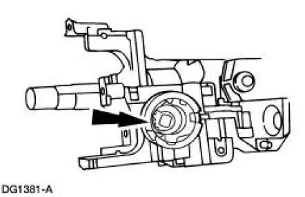
9. CAUTION: Install the steering column bearing so that the inner race is visible when installed.
NOTE: Use an appropriate bearing installer or socket.
Install the bearing in the lock cylinder housing.
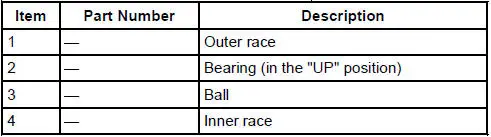
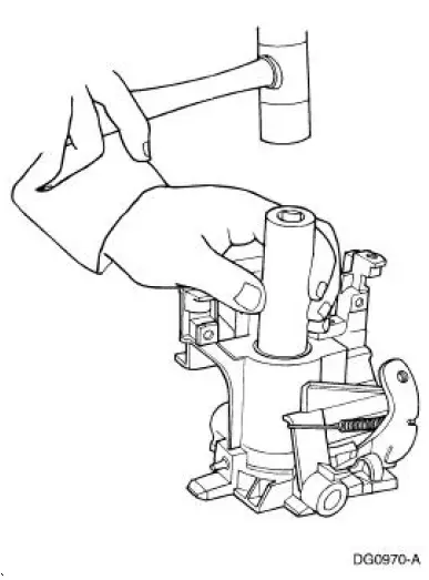
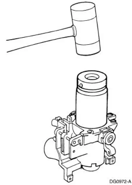
10. CAUTION: Install the steering column bearing so that the inner race is visible when installed
NOTE: Use an appropriate bearing installer or socket.
Install the bearing in the lock cylinder housing.

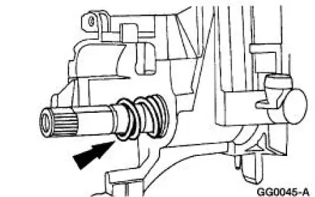
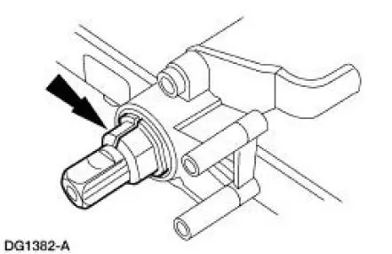
11. Position the shaft in the steering column lock cylinder housing.
- Install the bearing tolerance ring on the steering column shaft.
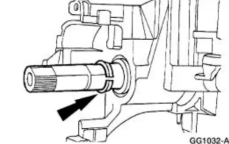
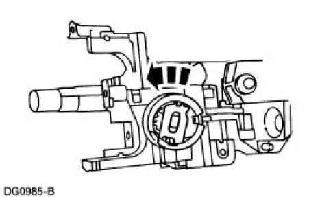
12. Install the bearing sleeve.
13. Install the upper bearing spring.
14. Install the snap ring.
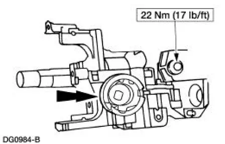
15. Install the tilt pivot screws loosely and position the actuator housing in a vise.
- Lubricate the pivot screws with Ignition Lock Grease F0AZ-19584-A or equivalent meeting Ford specification ESA-M1C232-A.
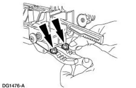
16. Place two nuts or spacers to hold the lock levers away from the actuator housing.
17. NOTE: Lubricate the lock cylinder housing pivot bushings with Ignition Lock Grease F0AZ- 19584-A or equivalent meeting Ford specification ESA-M1C232-A.
Install the lock cylinder housing.
- Position the lock cylinder housing and the shaft assembly on the actuator housing.
- Make sure the upper and lower lock actuators are aligned.
- Install and compress the steering column position spring.
- Align the lock cylinder housing bushings with the pivot screws and tighten the screws.
- Using a long thin screwdriver, remove the nuts installed under the lock levers.
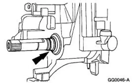
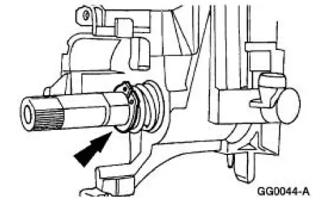
18. Install the bearing tolerance ring.
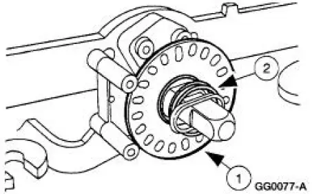
19. Install the sensor ring.
1. Install the sensor ring.
2. Install the lower bearing spring.
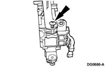
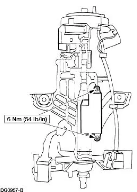
20. Install the ignition switch. Align the ignition switch with the slot and index-mark on the actuator housing.
- Install the screws.
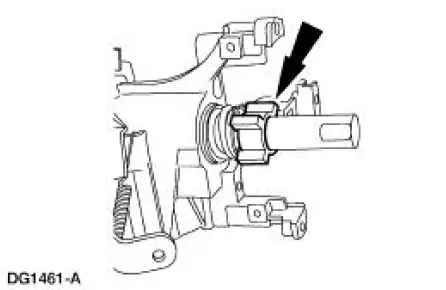
21. NOTE: The narrow section of the keyhole in the lock gear should be in the one o'clock position.
Install the lock gear.
- Use Ignition Lock Grease F0AZ-19584-A or equivalent meeting Ford specification ESAM1C232- A to coat the lock gear.
22. Install the lock housing bearing.
- The narrow section of the keyhole should be in the one o'clock position, with the tab inboard at the three o'clock position, and rotate it counterclockwise.
- Lubricate the lock housing bearing with Ignition Lock Grease F0AZ-19584-A or equivalent meeting Ford specification ESA-M1C232-A.
23. Install the upper bearing retainer firmly to engage the four retention tabs into the lock housing.
24. Install the turn indicator cancel cam.
25. WARNING: To avoid risk of serious personal injury, follow all warnings, cautions, notes and instructions in the steering column removal and installation procedure.
Install the steering column. For additional information, refer to Column in this section.
 Disassembly
1. WARNING: To avoid risk of serious personal injury, follow all
warnings, cautions,
notes and instructions in the driver air bag removal and installation procedure.
Remove the steering column (3C ...
 Steering Column Switches
Torque Specifications
Steering Column Switches (DESCRIPTION AND OPERATION)
The steering column switches system consists of the following components:
multifunction switch (13K359)
key release butto ...
Other materials:
Component Tests
Battery-Load Test
1. With the engine running, turn the A/C on, the blower motor on high
speed and the headlamps
on high beam.
2. Increase the engine speed to approximately 2,000 rpm. The voltage
should increase a minimum
of 0.5 volt above the ba ...
Overdrive Servo
Special Tool(s)
Remover/Installer, Servo
Piston
307-251 (T92P-70023-A)
Removal
1. Remove the main control valve body. For additional information, refer
to Main Control Valve
Body in this section.
2. NOTE: If the tool is not available, e ...
Economical driving
Fuel economy is affected by several things, such as how you drive, the
conditions you drive under and how you maintain your vehicle.
There are some things to keep in mind that may improve your fuel
economy:
• Accelerate and slow down in a smooth, moderate f ...
