Ford Mustang (1999-2004) Service Manual: Disassembly
1. WARNING: To avoid risk of serious personal injury, follow all warnings, cautions, notes and instructions in the driver air bag removal and installation procedure.
Remove the steering column (3C529). For additional information, refer to Column in this section.
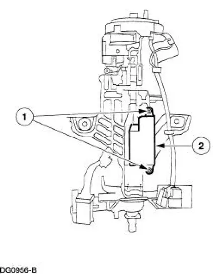
2. Remove the ignition switch (11572).
1. Remove the screws.
2. Remove the ignition switch.
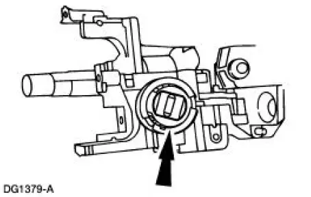
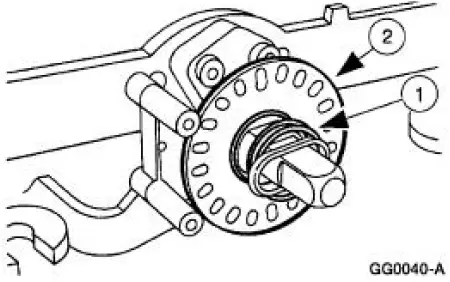
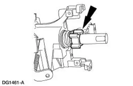
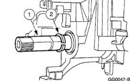
3. CAUTION: Carefully note the position of the steering column lock gear, bearing and retainer prior to removal.
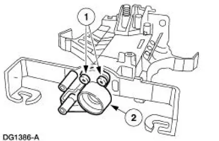
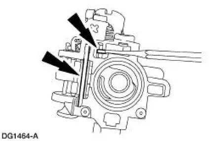
Remove the bearing retainer (3D681).
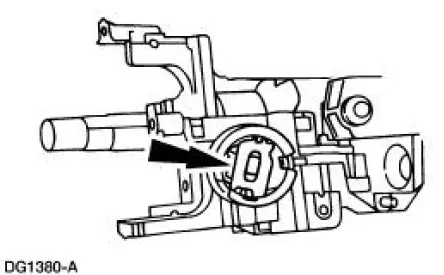
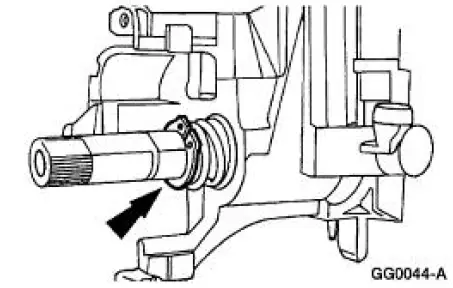
4. Remove the lock housing bearing (3E700).
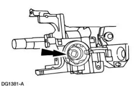
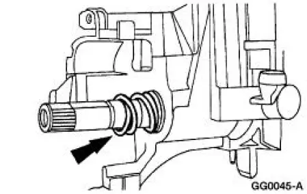
5. Remove the lock gear (3E717).
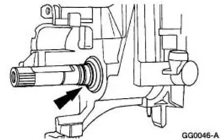
6. Remove the sensor ring.
1. Remove the lower bearing spring.
2. Remove the sensor ring.
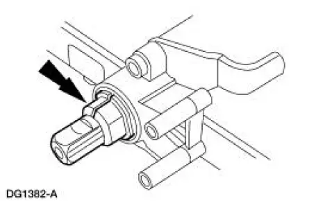
7. Remove the lower bearing tolerance ring from the shaft.
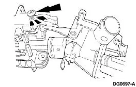
8. Remove the two tilt pivot screws.
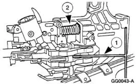
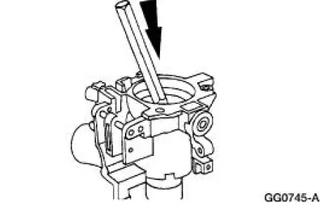
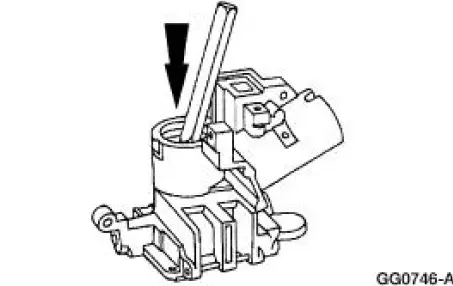
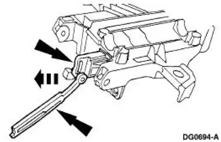
9. WARNING: Steering column position spring is under tension and can come out with great force.
Remove the lock cylinder housing and shaft assembly from the actuator housing (3F723).
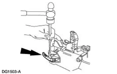
1. Pry up on the lock actuator lever (LH) (3D653) using a shop fabricated tool.
2. Remove the position spring (3D655).
10. Remove the turn indicator cancel cam.
11. Remove the snap ring.
12. Remove the upper bearing spring (3520).
13. Remove the bearing sleeve (3518).
14. Remove the lower bearing tolerance ring (3L539).
1. Slide the steering column shaft in toward the lock cylinder housing (3511).
2. Slide the steering column bearing tolerance ring from the steering column shaft and remove the shaft.
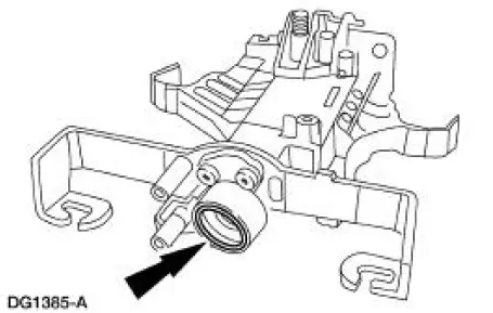
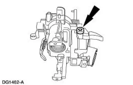
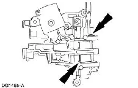
15. Using a suitable punch, remove the lower bearing (3517) from the lock cylinder housing.
16. Use a suitable punch to remove the bearing from the lock cylinder housing.
17. Remove the lower bearing and sleeve.
18. Remove the lower bearing retainer (3D681).
1. Remove the three bolts.
2. Remove the lower bearing retainer.
19. Remove the upper lock lever actuator (3E715) and the lower lock lever actuator.
20. Remove the ignition lock cylinder lockout lever.
21. Remove the lock actuator lever return spring.
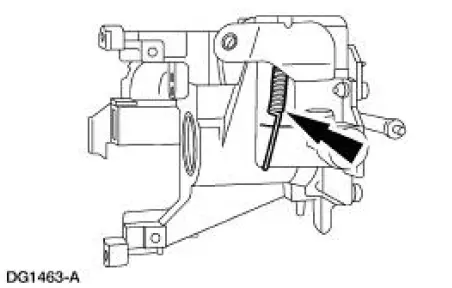
22. Using a pin punch, remove the pin and lock actuator lever.
23. Using a pin punch, remove the pin and locking lever cam.
24. NOTE: Do not remove the tilt lock levers if not required.
Using a pin punch, remove the pin, tilt locking levers and springs.
 Steering Column (Disassembly and Assembly)
Special Tool(s)
Steering Column Locking Lever
Tool
(Shop Fabricated)
...
 Assembly
1. Install the locking lever cam and pin.
2. Install the lock actuator lever and pin.
3. Install the lock actuator lever return spring.
4. Install the ignition lock cylinder lockout lever.
5. ...
Other materials:
Overdrive Servo
Special Tool(s)
Remover/Installer, Servo
Piston
307-251 (T92P-70023-A)
Removal
1. Remove the main control valve body. For additional information, refer
to Main Control Valve
Body in this section.
2. NOTE: If the tool is not available, e ...
Idle Air Control (IAC) Valve - 3.8L
Removal
1. Disconnect the battery ground cable. For additional information,
refer to Section.
2. NOTE: Discard the idle air control (IAC) valve gasket.
Remove the IAC valve.
Disconnect the connector.
Remove the two bolts, the IAC valve and ...
Safety Belts
PRINCIPLES OF OPERATION
WARNING: Always drive and ride with your seat back upright
and the lap belt snug and low across the hips
WARNING: To reduce the risk of injury, make sure children sit
where they can be properly restrained.
WARNING: Never let a passenger ...
