Ford Mustang (1999-2004) Service Manual: Brake System (Diagnosis and Testing)
Refer to Wiring Diagrams Cell 60, Instrument Cluster for schematic and connector information.
Refer to Wiring Diagrams Cell 97, Daytime Running Lamps for schematic and connector information.
Special Tool(s)
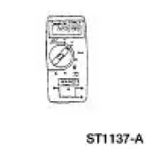 |
73 Digital Multimeter 105-R0051 or Equivalent |
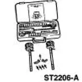 |
ABS Brake and Pressure Test Kit 107-02350 or Equivalent |
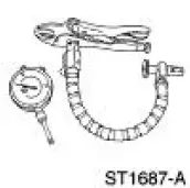 |
Tire and Wheel Runout Gauge Set 134-00199 or Equivalent |
- Inspection and Verification
- Vibration When Brakes are Applied
- Symptom Chart
- Pinpoint Tests
- Component Tests
 Brake System (Description and Operation)
Component Locations
+
The vehicle is equipped with a vacuum-assisted or a hydro-boost power braking
system.
The braking system is a front-to-rear split hydraulic system.
The front wheel b ...
 Inspection and Verification
WARNING: Use of any other than the approved DOT 3 brake fluid will
cause permanent
damage to brake components and will render the brakes inoperative.
WARNING: Brake fluid contains polyglycol ethers ...
Other materials:
Heated Window Grid Wire Repair
Material
Item
Specification
Dark Walnut Metallic Acrylic
Lacquer Touch-up Paint
ALBZ-19500-5858A or
equivalent
ESR-M2-P100-
C
Rear Window Defroster Repair
D8AZ-19562-AA or equivalent
WSB-M4J58-B
1. NOTE: A single break or an ...
Supply Manifold
Removal
WARNING: Do not smoke or carry lighted tobacco or open flame of any
type when
working on or near any fuel related components. Highly flammable mixtures are
always present
and can ignite. Failure to follow these instructions can result in personal
in ...
Cleaning the exterior
Wash your vehicle regularly with cool or lukewarm water and a neutral
pH shampoo, such as Motorcraft® Detail Wash.
• Do not use a commercial or high-pressure wand on the surface or
edge of stripes and graphics. This can cause damage to the film and
cause th ...
