Ford Mustang (1999-2004) Service Manual: Charge Air Cooler
Material
| Item | Specification |
| Silicone Gasket and Sealant F7AZ-19554-EA or equivalent | WSE-M4G323-EA |
Removal and Installation
1. Drain the supercharger coolant. For additional information, refer to Section.
2. Release the fuel pressure. For additional information, refer to Section.
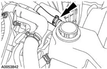
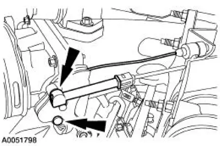
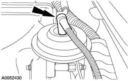
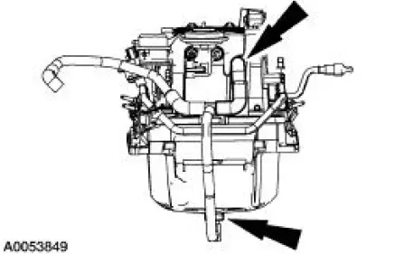
3. Disconnect the supercharger degas hose.
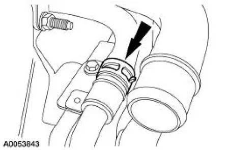
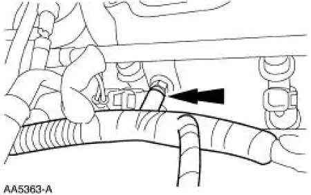
4. Disconnect the coolant hose.
5. Remove the supercharger belt. For additional information, refer to Section.
6. Remove the air cleaner outlet tube. For additional information, refer to Section.
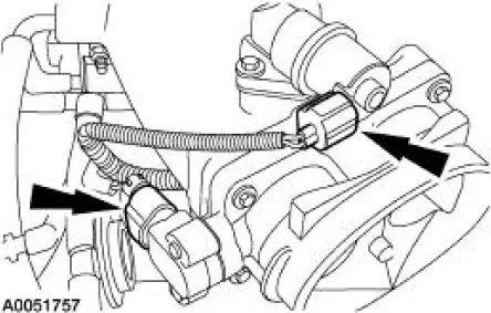
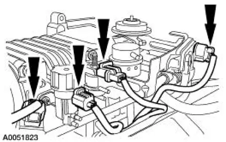
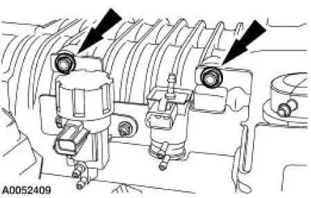
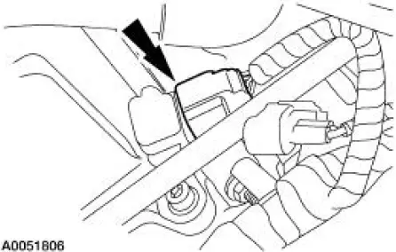
7. Disconnect the throttle position (TP) sensor and the idle air control (IAC) valve electrical connectors.
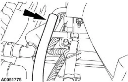
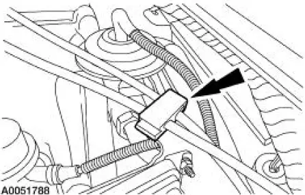
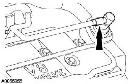
8. Disconnect the vacuum hose.
9. Disconnect the fuel supply spring lock coupler.
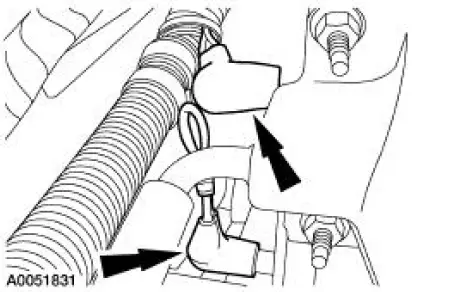
10. Disconnect the accelerator controls.
- Disconnect the accelerator cable.
- If equipped, disconnect the speed control cable.
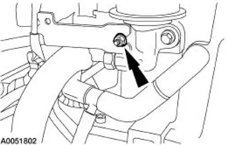
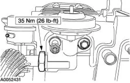
11. Remove the accelerator cable bracket bolts.
12. Remove the throttle body and spacer assembly.
13. Release the clip and position the accelerator cable bracket and the cables aside.
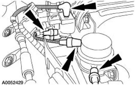
14. Disconnect the electrical connectors from the fuel pulse damper, EGR vacuum regulator solenoid, supercharger bypass vacuum solenoid, and the differential pressure feedback EGR system.
15. Disconnect the vacuum hoses from the differential pressure feedback EGR system.
16. Disconnect the vacuum hoses from the supercharger bypass vacuum solenoid, and the actuator.
17. Disconnect the vacuum hoses from the fuel pulse damper and the EGR vacuum regulator solenoid.
18. Disconnect the vacuum hose from the EGR valv
19. Disconnect the vacuum hoses at the back of the supercharger and position the vacuum harness aside.
20. Remove the vacuum accessory bracket mounting nut.
21. Remove the mounting bolts, and the vacuum accessory bracket.
22. Disconnect the exhaust manifold to EGR valve tube.
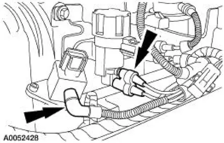
23. Disconnect the barometric pressure (BARO) sensor electrical connector.
24. Disconnect the positive crankcase ventilation (PCV) hose.
25. Separate the fuel charging wiring harness from the fuel injection supply manifold in four places and position the harness aside.
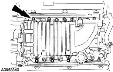
26. Remove the ten bolts, the intake manifold, supercharger and fuel supply manifold as an assembly.
27. Disconnect and remove the PCV hoses.
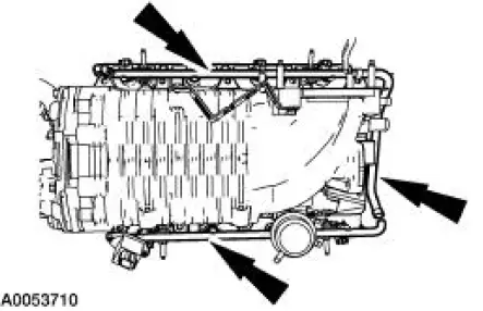
28. Remove the coolant supply and return manifold.
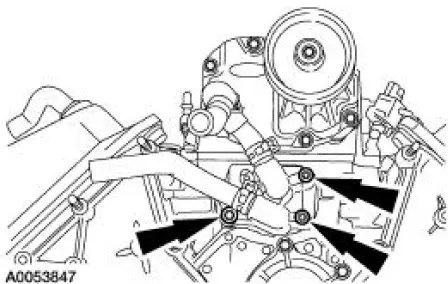
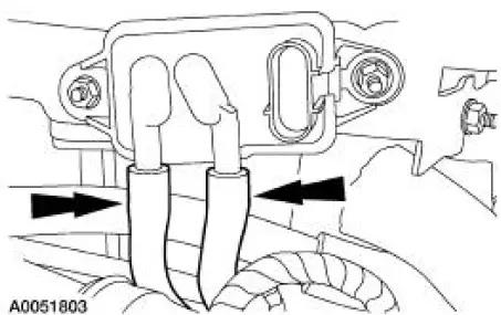
29. Remove the coolant supply and return tubes and seals.
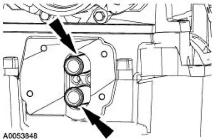
29. Remove the coolant supply and return tubes and seals.
31. Remove the fuel supply manifold and fuel injectors as an assembly.
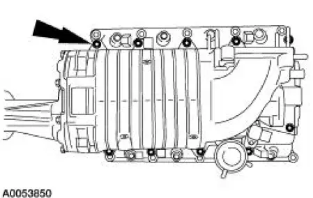
32. Remove the bolts, the supercharger and charge air cooler (CAC) assembly.
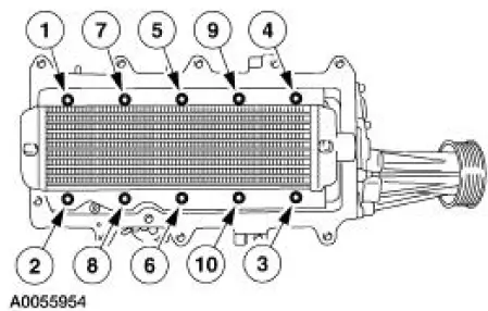
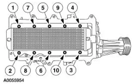
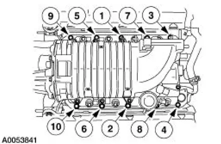
33. Remove the bolts and the CAC in the sequence shown.
34. Inspect the CAC plenum gasket and install a new gasket if necessary.
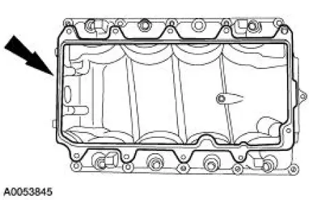
35. To install, reverse the removal procedure 36. Apply a bead of sealant in the areas shown on the supercharger flange between the CAC and the supercharger.

37. NOTE: Once the torque procedure has been started, final tightening must be finished within five minutes maximum.
Tighten the CAC bolts in the sequence shown in two stages.
1. Tighten to 2 Nm (18 lb-in).
2. Tighten to 6 Nm (53 lb-in).
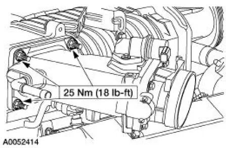
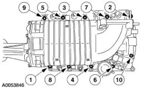
38. Tighten the supercharger and CAC cooler assembly-to-lower intake manifold bolts in the sequence shown in three stages.
1. Tighten to 2 Nm (18 lb-in).
2. Tighten to 25 Nm (18 lb-ft).
3. Tighten an additional 90 degrees.
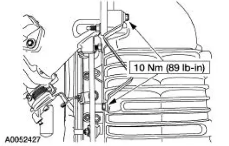
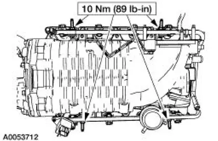
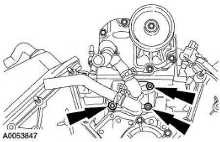
39. Tighten the coolant supply and return manifold in two stages.
1. Tighten to 10 Nm (89 lb-ft).
2. Tighten an additional 90 degrees.
40. NOTE: Inspect the intake manifold gaskets and install new gaskets, if necessary.
Tighten the lower intake manifold bolts in the sequence shown.
41. Fill and bleed the supercharger cooling system.
 Air Intake Scoop Bracket
Removal and Installation
1. Remove the air intake scoop. For additional information, refer to Air
Intake Scoop in this section.
2. Remove the air intake scoop bracket nut at the throttle body.
...
 Evaporative Emissions
General Specifications
Torque Specifications
...
Other materials:
Pinpoint Test D: LFC 15/DTC B 1887- Driver Air Bag Circuit Shorted to
Ground
Normal Operation
The restraints control module (RCM) checks for driver air bag circuit
shorts to ground by monitoring the
voltage of circuits 614 (GY/OG) and 615 (GY/WH) at pins 3 and 4. If the RCM
detects a short to
ground on either of these pins, it w ...
Accelerator Cable Bracket - 3.8L
Removal and Installation
1. Disconnect the speed control cable from the throttle body and the bracket.
For additional
information, refer to Section.
2. Disconnect the accelerator cable from the throttle body by rotating the
throttle body full open
and align ...
Troubleshooting
Your SYNC system is easy to use. However, should questions arise, see
the tables below.
Use the website at any time to check your phone’s compatibility,
register your account and set preferences as well as access a
customer representative via an online chat ...
