Ford Mustang (1999-2004) Service Manual: Convertible Top (Diagnosis and Testing)
Refer to Wiring Diagrams Cell 103 , for schematic and connector information.
Special Tool(s)
 |
73 III Automotive Meter 105-R0057 or equivalent |
Principles of Operation
The convertible top will only operate with the parking brake engaged and the ignition switch in the RUN position. When the parking brake is engaged, the raise and lower relay coils are grounded through the parking brake switch. The convertible top switch supplies power to the raise or lower relay coil when raise or lower is selected. This power energizes the coil causing the relay contacts to close which supplies battery power to the convertible top motor/pump assembly. The normal state of the relay is connected to ground. When the raise or lower relay is operating, the other relay remains in its normal state supplying the motor/pump ground.
Convertible Top Adjustments
The convertible top adjustments must be made by a qualified technician.
Inspection and Verification
1. Verify the customer concern by operating the system.
2. Visually inspect for obvious signs of mechanical or electrical damage.
Visual Inspection Chart
| Mechanical | Electrical |
|
|
3. If an obvious cause for an observed or reported concern is found, correct the cause (if possible) before proceeding to the next step.
4. If the concern is not visually evident, verify the symptom and refer to the Symptom Chart.
Symptom Chart
| Condition | Possible Sources | Action |
|
|
|
|
|
|
|
|
|
|
|
|
PINPOINT TEST A: THE CONVERTIBLE TOP DOES NOT RAISE/LOWER
| Test Step | Result / Action to Take |
| A1 CHECK THE CONVERTIBLE TOP OPERATION | Yes Go To Pinpoint Test C . No GO to A2 . |
NOTE: The parking brake must be applied for the convertible top system to operate.
|
|
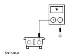
| A2 CHECK THE POWER SUPPLY TO THE CONVERTIBLE TOP SWITCH | Yes GO to A3 . No REPAIR circuit 296 (WH/PK). TEST the system for normal operation. |
|
|
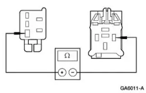
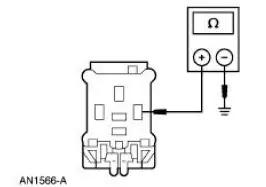
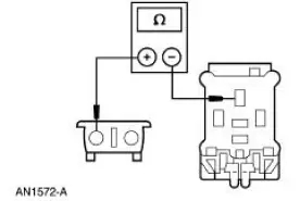
| A3 CHECK CIRCUIT 588 (VT) FOR AN OPEN | Yes GO to A4 . No GO to A5 . |
|
|
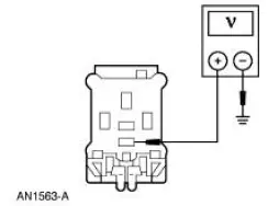
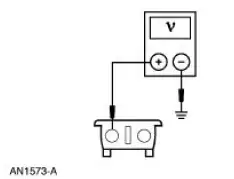
| A4 CHECK CIRCUIT 688 (GY/LB) FOR VOLTAGE | Yes GO to A9 . No GO to A8 . |
|
|
| A5 CHECK CIRCUIT 588 (VT) FOR OPEN | Yes INSTALL a new convertible top switch. REFER to Convertible Top Switch in this section. TEST the system for normal operation. No REPAIR Circuit 588 (VT). TEST the system for normal operation. |
|
|
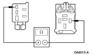
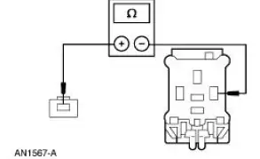
| A6 CHECK CIRCUIT 688 (GY/LB) FOR OPEN | Yes INSTALL a new convertible top switch. REFER to Convertible Top Switch in this section. TEST the system for normal operation. No REPAIR circuit 688 (GY/LB). TEST the system for normal operation. |
|
|
| A7 CHECK THE BATTERY SUPPLY TO THE RELAYS | Yes GO to A8 . No REPAIR circuit 170 (RD/LB). TEST the system for normal operation. |
|
|
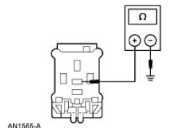
| A8 CHECK CIRCUIT 1205 (BK) FOR AN OPEN | Yes GO to A9 . No REPAIR the circuit. TEST the system for normal operation. |
|
|
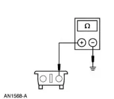
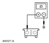
| A9 CHECK FOR PARKING BRAKE GROUND | Yes GO to A11 . Yes GO to A10 . |
|
|
| A10 CHECK THE PARKING BRAKE SWITCH | Yes INSTALL a new parking brake switch. REFER to Section . TEST the system for normal operation. No REPAIR the circuit in question. TEST the system for normal operation. |
|
|
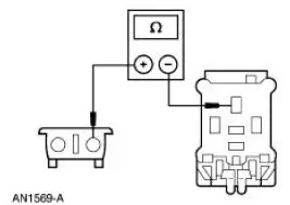
| A11 CHECK THE CONVERTIBLE TOP MOTOR LOWER CIRCUIT | Yes GO to A13 . No GO to A12 . |
|
|
| A12 CHECK CIRCUIT 902 (YE) FOR AN OPEN | Yes INSTALL a new lower relay. TEST the system for normal operation. No REPAIR the circuit. TEST the system for normal operation. |
|
|
| A13 CHECK THE LOWER INPUT TO THE MOTOR | Yes GO to A14 . No INSTALL a new lower relay. TEST the system for normal operation. |
|
|
| A14 CHECK THE CONVERTIBLE TOP MOTOR RAISE CIRCUIT | Yes GO to A16 . No GO to A15 . |
|
|
| A15 CHECK CIRCUIT 903 (RD) FOR AN OPEN | Yes INSTALL a new raise relay. TEST the system for normal operation. No REPAIR the circuit. TEST the system for normal operation. |
|
|
| A16 CHECK THE RAISE INPUT TO THE MOTOR | Yes INSTALL a new convertible top motor; REFER to Hydraulic System, Lift Cylinder and Motor in this section. TEST the system for normal operation. No INSTALL a new raise relay. TEST the system for normal operation. |
|
PINPOINT TEST B: THE CONVERTIBLE TOP HESITATES/COMES UP UNEVEN
| Test Step | Result / Action to Take |
| B1 CHECK THE CONVERTIBLE TOP UP/DOWN OPERATION | Yes ADJUST the convertible top linkage. TEST the system for normal operation. No GO to B2 |
NOTE: The parking brake must be applied for the convertible top system to operate.
|
|
| B2 CHECK THE MOTOR OPERATION | Yes Go To Pinpoint Test A . No GO to B3 . |
|
|
| B3 CHECK THE CONVERTIBLE TOP LINKAGE | Yes Go To Pinpoint Test D . No ADJUST the convertible top linkage. TEST the system for normal operation. |
|
PINPOINT TEST C: THE CONVERTIBLE TOP DOES NOT RAISE OR DOES NOT GO UP ALL THE WAY
| Test Step | Result / Action to Take |
| C1 CHECK THE CONVERTIBLE TOP OPERATION | Yes GO to C2 . No Go To Pinpoint Test A . |
NOTE: The parking brake must be applied for the convertible top system to operate.
|
|
| C2 CHECK THE CONVERTIBLE TOP LINKAGE | Yes ADJUST the convertible top linkage. TEST the system for normal operation. No Go To Pinpoint Test D . |
|
PINPOINT TEST D: THE CONVERTIBLE TOP HYDRAULIC SYSTEM
| Test Step | Result / Action to Take |
| D1 CHECK THE FLUID LEVEL | Yes GO to D3 . No GO to D2 . |
NOTE: The fluid level should be even with the bottom of the filler plug hole.
|
|
| D2 CHECK THE HYDRAULIC SYSTEM FOR LEAKS | Yes REPAIR the leaking fittings or INSTALL new hoses as necessary. TEST the system for normal operation. No GO to D3 . |
|
|
| D3 BLEED THE HYDRAULIC SYSTEM | Yes OPERATE the convertible top up and down three times. INSPECT the hydraulic system for leaks or loss of fluid. REPAIR as necessary if loss of fluid is detected. No GO to D4 . |
|
|
| D4 CHECK THE CONVERTIBLE TOP | Yes ADJUST the convertible top. INSTALL the hydraulic system; REFER to Hydraulic System, Lift Cylinder and Motor in this section. TEST the system for normal operation. No GO to D5 |
|
|
| D5 CHECK THE HYDRAULIC SYSTEM OUT OF THE VEHICLE | Yes CHECK all fittings and hoses for leaks. REPAIR as necessary if loss of fluid is detected. INSTALL the hydraulic system; REFER to Hydraulic System, Lift Cylinder and Motor in this section. TEST the system for normal operation. No GO to D6 . |
|
|
| D6 CHECK THE LIFT CYLINDERS | Yes INSTALL a new motor/pump assembly. REFER to Hydraulic System, Lift Cylinder and Motor in this section. TEST the system for normal operation. No INSTALL a new lift cylinder. REFER to Hydraulic System, Lift Cylinder and Motor in this section. TEST the system for normal operation. |
|
 Convertible Top (Description and Operation)
Rear Window Glass Assembly
The convertible top assembly is equipped with a rear window glass
assembly. The rear window glass
assembly is permanently attached to the folding top rear ...
 System Bleeding
1. If required, remove the hydraulic system from the vehicle. Refer
to Hydraulic System, Lift
Cylinder and Motor in this section.
2. Remove the fill plug at the end of the hydraulic pump.
3. ...
Other materials:
Climate Control System (Description and Operation)
WARNING: To avoid accidental deployment and possible injury, the air
bag system
backup power supply must be depleted before repairing any climate control
components. To
deplete the backup power supply, disconnect the battery ground cable and wait
one minute ...
Shift Point Road Test
This test verifies that the shift control system is operating
correctly.
1. Bring engine and transmission up to normal operating temperature.
2. Operate vehicle with transmission range selector lever in (D)
position.
3. NOTE: Shift speed ranges a ...
Bezel
Removal
1. Remove the shifter top control panel.
2. Disconnect the electrical connectors.
3. Remove the shifter bezel.
4. Remove the bulb from the bezel.
5. Disconnect the connector.
6. CAUTION: Extra force may be needed to lift up on the handle. Do not ...
