Ford Mustang (1999-2004) Service Manual: Countershaft Bearing
Special Tool(s)
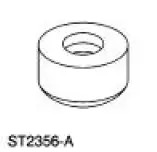 |
Bearing Replacer 308-061 (T77J-7025-L) |
 |
Front Bearing Replacer 308-062 (T77J-7025-M) |
 |
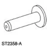
Mainshaft Front Bearing Replacer 308-081 (T82T-7003-DH) |
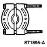 |
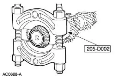
Pinion Bearing Cone Remover 205-D002 (D79L-4621-A) or Equivalent |
 |
Pinion Bearing Cone Replacer 205-011 (T57L-4621-B) |
 |
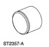
Remover and Replacer Tube 308-024 (T75L-7025-B) |
 |
Remover and Replacer Tube 308-052 (T77J-7025-B) |
Disassembly
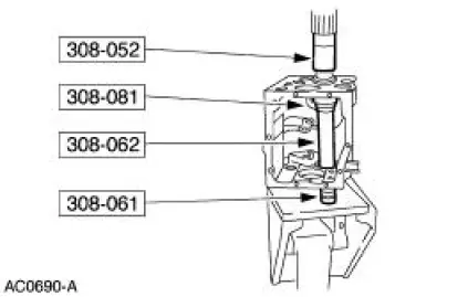
1. Using the special tool and a press, remove the countershaft bearing assembly (7F431).
2. CAUTION: Failure to correctly support the case (7005) during bearing race removal will result in permanent distortion of the case.
NOTE: Remove the front countershaft bearing race only if damaged or worn.
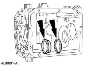
Using the special tools and a press, remove the bearing race and the countershaft front bearing seal (7693).
Assembly
NOTE: Position the countershaft in the transmission case before installing the rear countershaft bearing.
1. Install the countershaft front bearing seal on the bearing race.
2. Coat the outside diameter of the bearing race with sealer.
- Use Threadlock and Sealer E0AZ-19554-AA or equivalent meeting Ford specification WSK-M2G351-5A.
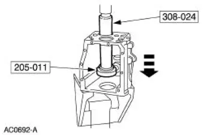
3. CAUTION: Failure to correctly support the case during bearing race installation will result in permanent distortion of the case.
Using the special tools and a press, install the bearing race.
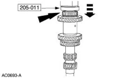
4. Using the special tool and a press, install the front countershaft bearing.
 Output Shaft
Special Tool(s)
Pinion Bearing Cone Remove
205-D002 (D79L-4621-A) or
Equivalent
Spiral Snap Ring Replacer
308-096 (T85P-7025-A)
Disassembly
1. Using the special tool a ...
 Synchronizers
Disassembly
NOTE: This procedure applies to all synchronizer assemblies
(7124). The synchronizers are slightly
different in design. Notation is made where procedural differences occur.
1. On the ...
Other materials:
Universal Joints
The universal joints are:
lubed-for-life design and require no lubrication.
equipped with nylon thrust washers, located at each base of the bearing
cup, which control end
play, position the needle bearing and improve grease movement.
Item ...
Transmission Electronic Control System
The powertrain control module (PCM) and its input/output network
control the following transmission
operations:
Shift timing
Line pressure (shift feel)
Torque converter clutch
The transmission control is separate from the engine control s ...
Clutch (Description and Operation)
The primary function of the clutch is to couple and uncouple engine power
to the transmission upon
driver command.
The clutch is a single plate, dry friction clutch disc. The clutch
disc has a splined hub (with
integral torsional dampening springs ...
