Ford Mustang (1999-2004) Service Manual: Fittings - R-Clip
Material
| Item | Specification |
| SAE 5W-20 Super Premium Synthetic Blend Motor Oil XO-5W20-QSP or equivalent | WSS-M2C153- H |
Disconnect
WARNING: Do not smoke or carry lighted tobacco or open flame of any type when working on or near any fuel-related components. Highly flammable mixtures are always present and may be ignited, resulting in possible personal injury.
WARNING: Fuel in the fuel system remains under high pressure even when the engine is not running. Before servicing or disconnecting any of the fuel lines or fuel system components, the fuel system pressure must be relieved to prevent accidental spraying of fuel, causing possible personal injury or a fire hazard.
CAUTION: Do not use any tools. The use of tools may cause a deformity in the clip components which may cause fuel leaks.
1. Relieve the fuel system pressure. For additional information, refer to Pressure Relief in this section.
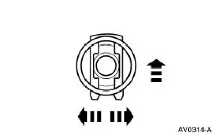
2. Remove the shipping tab by bending.
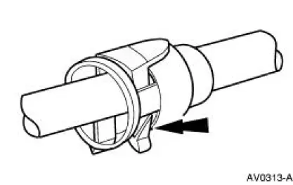
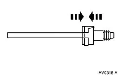
3. Spread the R-clip legs and push the clip into the fitting.
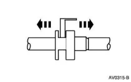
4. Separate the fitting from the tube.
Connect
1. NOTE: Apply a light coat of clean engine oil.
Clean and inspect the fitting and the tube for damage.
2. Insert the R-clip into the fitting.
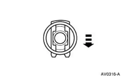
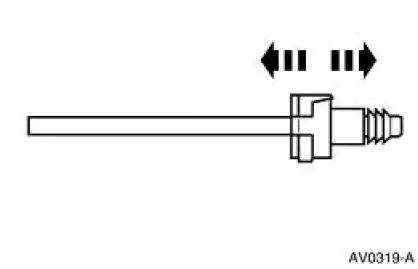
3. Insert the tube in the fitting and push together until a click is heard.
4. Pull on the connection to make sure it is fully engaged.
 Fuel Line Fittings - Push Connect
Special Tool(s)
Disconnect Tool, Spring Lock
Coupling
310-S039 (T90T-9550-S)
Material
Item
Specification
SAE 5W-20 Super Premium
Blend Motor Oil
XO-5W20-QSP or equiv ...
 Fittings - Vapor Tube
Disconnect
1. WARNING: The evaporative emission system contains fuel vapor and
condensed
fuel vapor. Although not present in large quantities, it still presents the
danger of
explosion or fire. Disc ...
Other materials:
Dual-Function Pressure Switch (4.6L)
The dual-function pressure switch is used to interrupt A/C compressor
operation in the event of high system discharge pressures.
The dual-function pressure switch is mounted on a Schrader valve-type
fitting on the high
pressure side of the A/C manifold ...
Window Regulator - Power
Removal
1. Remove the door window glass. For additional information, refer to
Window Glass-Door in this
section.
2. Disconnect the electrical connector.
3. Remove the channel.
4. Remove the regulator.
Installation
1. To install, reverse the r ...
Motorcraft part numbers
1For spark plug replacement, see your authorized dealer. See Scheduled
Maintenance
Information for the appropriate intervals for changing the spark plugs.
Replace the spark plugs with ones that meet Ford material and design
specifications for
your vehicle, ...
