Ford Mustang (1999-2004) Service Manual: Front End Body Panels
Torque Specifications
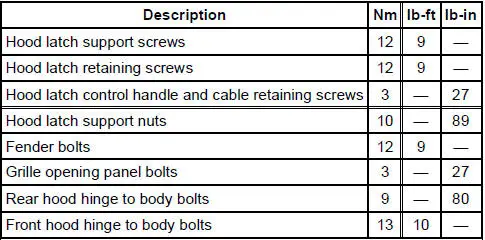
Front End Body Panels
The front end body panel components consist of the following:
- air deflectors
- cowl grille
- fenders
- fender splash shields
- hood
- hood hinges
- hood weatherstrip
- radiator grille opening panel
Fender
Removal and Installation
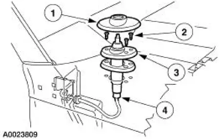
1. On the RH fender, remove the antenna base.
1. Remove the antenna base cap.
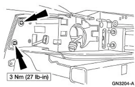
2. Remove the screws.
3. Remove the antenna base.
4. Disconnect the antenna cable from the antenna base.
2. Remove the front bumper cover. For additional information, refer to Section.
3. Remove the screw, the two pin-type retainers and the front rocker panel moulding.
4. Remove the fender splash shield screw.
5. NOTE: Position the fender splash shield aside.
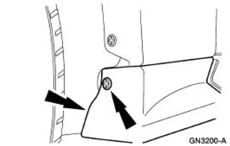
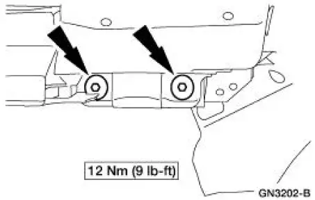
Remove the lower fender bolts and, if equipped, remove the shims.
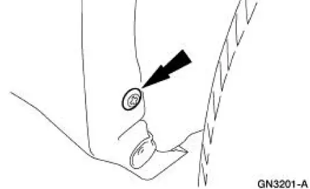
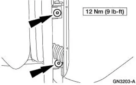
6. Through the door opening, remove the inner fender bolts.
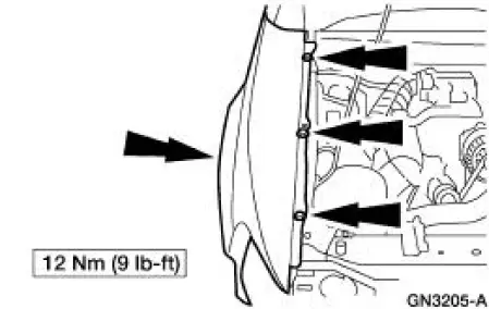
7. Remove the radiator grille opening panel to fender bolts.
8. Remove the upper bolts and the fender.
9. NOTE: On the RH fender, feed the antenna cable through the fender opening.
To install, reverse the removal procedure.
- Check the fender alignment and adjust as needed.
Radiator Grille Opening Panel
Removal and Installation
1. Remove the front bumper cover. For additional information, refer to Section.
2. Remove the eight bolts (four on each side) and the radiator grille opening panel.
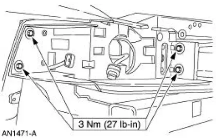
3. To install, reverse the removal procedure.
 Body System (Diagnosis and Testing)
Inspection and Verification
Leaks
NOTE: Trim will reveal the location of most leaks.
1. Remove any trim or carpet in the general area of the leak.
2. Road test or water test the vehicle.
3 ...
 Body Closures
General Specifications
Torque Specifications
Body Closures
The body closures consist of the following components:
door checks
front door
front door latch strikers
front door hinges ...
Other materials:
Brake Pads - Cobra
Removal
1. Remove brake fluid in the master cylinder reservoir until the
reservoir is half full.
2. Raise and support the vehicle.
3. Remove the tire and wheel assembly.
4. CAUTION: Install new pads if worn to or past the specified
thi ...
Installation
1. CAUTION: Do not allow grease, oil, brake fluid or other
contaminants to contact the
pad lining material. Do not install contaminated pads.
NOTE: Install all hardware supplied with pad kits.
Install the pads.
1. Install the new pad slippers. ...
Starter Drive and Flywheel Ring Gear Inspection
1. Remove the starter motor. For additional information, refer to Starter
Motor-3.8L or Starter
Motor-4.6L in this section.
2. Check the wear patterns on the starter drive gear and the flywheel ring
gear . If the wear pattern
is normal, install the sta ...
