Ford Mustang (1999-2004) Service Manual: Fuel System (Description and Operation)
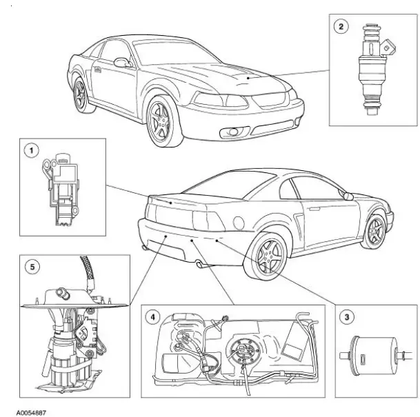
Component Location
WARNING: Do not smoke or carry lighted tobacco or open flame of any type when working on or near any fuel-related components. Highly flammable mixtures are always present and may be ignited, resulting in possible personal injury.
The vehicle:
- uses a returnless fuel system.
- is equipped with a multiport fuel injection (MFI) system.
- uses separately controlled fuel injectors (9F593) for each cylinder. The fuel injectors are mounted to the intake manifold.
- fuel injectors are supplied with pressurized fuel from the fuel pump (9350) through the fuel injection supply manifold (9D280).
- fuel injection supply manifold is controlled by the electronic fuel delivery module which is enabled by the powertrain control module (PCM) (12A650).
Fuel System
Refer to the Powertrain Control/Emissions Diagnosis (PC/ED) manual.
 Fuel System - General Information
General Specifications
...
 Pressure Relief
Special Tool(s)
Fuel Pressure Gauge
310-012 (T80L-9974-B)
WARNING: Do not smoke or carry lighted tobacco or open flame of any
type when
working on or near any fuel-related components. ...
Other materials:
Exhaust Manifold RH
Removal and Installation
1. Disconnect the battery ground cable. For additional information, refer to
Section.
2. Raise the vehicle. For additional information, refer to Section.
3. Remove the dual converter Y-pipe. For additional information, refer to
Sec ...
Glass, Frames and Mechanisms (Description and Operation)
Component Location
Windshield Glass
The windshield exterior mouldings are installed with the windshield
glass. The windshield exterior
mouldings cannot be replaced without removal of the windshield.
Window Regulator Control Switch
Power windows ...
Disconnect
1. Remove the A/C tube lock coupling clip (19E746), if equipped.
2. Fit the special tool to the spring lock coupling.
3. Push the tool into the cage opening to release the female fitting from the
A/C tube lock coupling
spring (19E576).
4. Pull the sprin ...
