Ford Mustang (1999-2004) Service Manual: Glass, Frames and Mechanisms (Diagnosis and Testing)
Refer to Wiring Diagrams Cell 100 , Power Windows for schematic and connector information.
Refer to Wiring Diagrams Cell 56 , Rear Window Defrost for schematic and connector information.
Special Tool(s)
 |
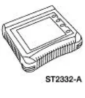
Worldwide Diagnostic System (WDS) 418-F224, New Generation STAR (NGS) Tester 418-F052, or equivalent diagnostic tool |
 |
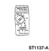
73III Automotive Meter 105-R0057 or equivalent |
 Glass, Frames and Mechanisms (Description and Operation)
Component Location
Windshield Glass
The windshield exterior mouldings are installed with the windshield
glass. The windshield exterior
mouldings cannot be replaced without removal of the ...
 Principles of Operation
Power Window Control
NOTE: Battery power and ground must be removed before disconnecting the
GEM connectors to
avoid setting false DTCs.
The driver power window one-touch down operation is contr ...
Other materials:
Pinpoint Test I: LFC 33/DTC B1933 - Passenger Air Bag Circuit Resistance
High
Normal Operation
The restraints control module (RCM) monitors the resistance of the
passenger air bag ignitor by
measuring the resistance between pins 6 and 7. If the RCM detects high
resistance between these
pins, it will store a diagnostic trouble cod ...
Symptom Chart
NOTE: New speed control diagnostic software is available in Version 12
or higher for the diagnostic
tool. When using this software, it is necessary to use Next Generation Speed
Control Adapter 007-
00586 with the diagnostic tool.
NOTE: Refer to the Wiring Di ...
Disassembly
1. CAUTION: Hand tighten the special tool to prevent gear damage.
CAUTION: Support the output shaft while using the press to prevent
damage to the
shaft or gears.
Using the special tool and a press, remove first gear, the output shaft rear
bearing ...
