Ford Mustang (1999-2004) Service Manual: Hydraulic Brake Actuation (Description and Operation)
CAUTION: Blistering or swelling of rubber brake components may indicate contamination of the brake fluid by a petroleum based substance. New rubber components must be installed in the hydraulic brake system if contaminated and the entire hydraulic brake system must be flushed with clean brake fluid to prevent recontamination.
This vehicle is equipped with a brake pedal actuated dual brake system. The system consists of the following:
- power brake booster (2005)
- brake master cylinder (2140)
- brake pressure control valve (2B091)
- disc brake calipers (2B120)
- rear disc brake calipers (2553)
- brake tubes and hoses
- anti-lock brake system (ABS) components
The dual brake system is split front and rear with the front wheel brakes comprising of one circuit and the rear wheel brakes, the other circuit.
Brake Fluid
WARNING: Brake fluid contains polyglycol ethers and polyglycols. Avoid contact with eyes. Wash hands thoroughly after handling. If brake fluid contacts eyes, flush with running water for 15 minutes. Get medical attention if irritation persists. If taken internally, drink water and induce vomiting. Get medical attention immediately.
Clean, fresh Ford High Performance DOT 3 Brake Fluid C6AZ-19542-AB or equivalent DOT 3 fluid meeting Ford specification ESA-M6C25-A is the only brake fluid that should be used in Ford vehicles.
- Do not reuse brake fluid drained or bled from the system.
- Do not use brake fluid that has been stored in an open container.
- Do not mix different types of brake fluid.
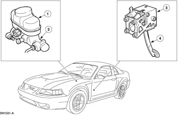
Brake Master Cylinder
The brake master cylinder is a dual piston type. The brake master cylinder operates as follows:
- When the brake pedal (2455) is depressed, pressure is applied by mechanical linkage to the primary and secondary piston.
- Brake master cylinder pistons apply hydraulic pressure to the two hydraulic circuits.
- Brake master cylinder will not be overhauled, a new master cylinder is installed only.
The brake master cylinder consists of:
- brake master cylinder reservoir (2K478)
- brake master cylinder body
Brake Master Cylinder Reservoir
NOTE: Whenever the brake master cylinder reservoir is removed from the brake master cylinder, new grommets must be installed.
The brake master cylinder reservoir :
- is mounted to the brake master cylinder.
- holds fluid supply for each brake master cylinder hydraulic piston.
- provides visual fluid level markings.
- contains the brake master cylinder fluid level sensor.
Brake Pressure Control Valve
The brake pressure control valve proportions the pressure to the rear brakes.
- When the brake pedal is applied, brake fluid pressure passes through the proportioning valves to the rear brake system until the valve split point is reached.
- Above its split point, the proportioning valve begins to reduce the hydraulic pressure to the rear brakes, creating a balanced braking condition between the front and rear brakes.
Brake Tubes and Hoses
CAUTION: Never use copper tubing. It is subject to fatigue, cracking and corrosion which could result in brake tube failure.
Steel tubing is used throughout the brake hydraulic system. All brake tube fittings must be correctly double flared to provide strong leakproof connections. When bending the tubing to fit the underbody or rear axle contours, be careful not to kink or crack the tube.
If a section of brake tube is damaged, the entire section must be removed and a new tube of the same type, size, shape and length installed.
When replacing hydraulic brake tubing, hoses, or connectors, tighten all connections securely. After installation, bleed the brake system.
 Hydraulic Brake Actuation
Torque Specifications
...
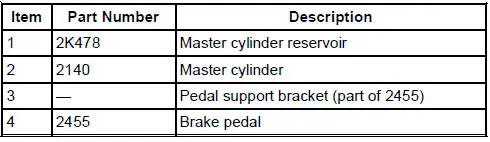
 Pedal and Bracket
Removal
1. Disconnect the battery ground cable (14301).
2. Remove the stoplight switch retaining pin.
3. Slide the stoplight switch (13480) and booster push rod from the brake
pedal pin.
4. Re ...
Other materials:
Fuel Charging Wiring Harness
Removal and Installation
WARNING: Do not smoke or carry lighted tobacco or open flame of any
type when
working on or near any fuel related components. Highly flammable mixtures are
always present
and may ignite. Failure to follow these instructions may resul ...
Removal
1. Remove the A/C compressor (19703). For additional information, refer to
Air Conditioning (A/C)
Compressor-3.8L or Air Conditioning (A/C) Compressor-4.6L in this section.
2. Remove the bolt.
1. Hold the A/C disc and hub assembly (19D786) with the special ...
Timing Drive Components
Special Tool(s)
Compressor, Valve Spring
303-567 (T97P-6565-AH)
Holding Tool, Crankshaft
303-448 (T93P-6303-A)
Aligner, Camshaft Position
303-557 (T96T-6256-B)
...
