Ford Mustang (1999-2004) Service Manual: Installation
1. Lubricate the lip of the wheel bearing oil seal
- Use Premium Long-Life Grease XG-1-C or equivalent meeting Ford specification ESAM1C75- B.
2. CAUTION: Do not damage the wheel bearing oil seal.
Install the two axle shafts.
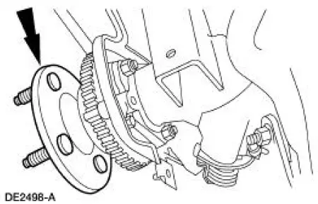
3. CAUTION: Do not damage the rubber O-ring in the axle shaft groove.
Install the U-washer.
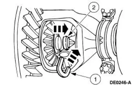
1. Position the two U-washers on the button end of the axle shaft.
2. Pull the axle shaft outward.
4. NOTE: If a new pinion shaft lock bolt is unavailable, coat the threads with Threadlock and Sealer EOAZ-19554-AA or equivalent meeting Ford specification WSK-M2G351-A5 prior to installation.
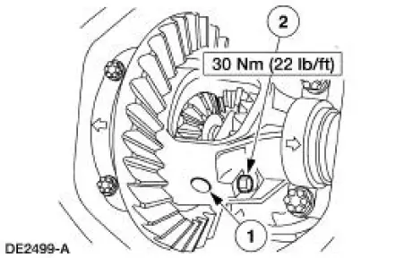
Install the differential pinion shaft.
1. Align the hole in the differential pinion shaft with the case lock bolt hole.
2. Install a new differential pinion shaft lock bolt.
5. Install the differential housing cover and fill the rear axle with the specified lubrication. For additional information, refer to Differential Housing Cover in this section.
6. Install the rear brake anti-lock sensor. .
7. Install the rear brakes. .
8. Install the tire and wheel assembly. 9. Lower the vehicle.
 Removal
1. Raise and support the vehicle.
2. Remove the wheel and tire assembly.
3. Remove the rear brake disc (2C026).
4. Remove the differential housing cover (4033) and drain the lubricant. For
addi ...
Other materials:
Idle Air Control (IAC) Valve - Mach I
Removal and Installation
1. Remove the air intake scoop. For additional
information, refer to Section.
2. Disconnect the idle air control (IAC) valve electrical connector.
3. Remove the bolts, the IAC valve and the gasket.
4. NOTE: Install a new ga ...
Headlamps
Refer to Wiring Diagrams Cell 85 , Headlamps for schematic and
connector information.
Special Tool(s)
73III Automotive Meter or
equivalent
105-R0057
Inspection and Verification
1. Verify the customer concern by operating the headlamps. ...
Interior mirror
WARNING: Do not adjust the mirror when your vehicle is
moving.
Note: Do not clean the housing or glass of any mirror with harsh
abrasives, fuel or other petroleum or ammonia based cleaning products.
You can adjust the interior mirror to your preference. Some ...
