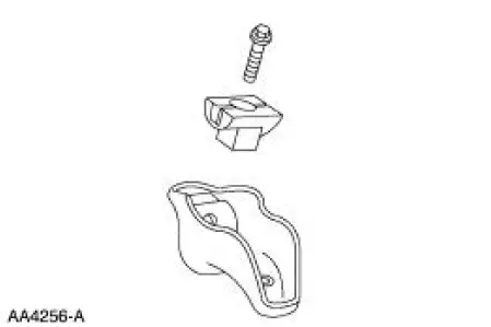
Ford Mustang (1999-2004) Service Manual: Rocker Arms - Inspection
CAUTION: Do not attempt to true surfaces by grinding. Check the rocker arm pad, side rails and seat for excessive wear, cracks, nicks or burrs. Check the rocker arm seat bolt for stripped or broken threads. Install new components as ncessary or possible damage may occur.
1. Inspect the rocker arm push rod bore for nicks, scratches, scores or scuffs. Install new components as necessary. Refer to the appropriate section in Group 303 for the procedure.

2. Inspect the pad at the valve end of the rocker arm for indications of scuffing or abnormal wear. If the pad is grooved, install a new rocker arm. Refer to the appropriate section in Group 303 for the procedure.
Push Rods - Cleaning
1. Clean the push rods (6565) in a suitable solvent. Blow out the oil passage in the push rods with compressed air.
 Sprockets
1. WARNING: To avoid the possibility of personal injury or damage
to the vehicle, do
not operate the engine with the hood open until the fan blade has been
examined for
possible cracks and separ ...
 Push Rods - Inspection
1. CAUTION: Do not attempt to straighten push rods.
Check the ends of the push rods for nicks, grooves, roughness or
excessive wear. Install new
push rods as necessary. Refer to the appropriate se ...
Other materials:
Installation
1. CAUTION: The timing chain procedures must be followed exactly or
damage to the
valve and pistons will result.
Compress the tensioner plunger, using an edge of a vise.
2. While holding the ratchet mechanism, push the ratchet arm back into the
tensioner ...
Rear Drive Axle and Differential
The axle housing assembly consists of a cast center section with two
steel tube assemblies and
a stamped differential housing cover (4033). The differential housing cover
uses silicone sealant
as a gasket.
The hypoid-design gearset consis ...
Heater Hose Coupling
Special Tool(s)
Remover, Heater Hose Inlet
Tube
412-042 (T85T-18539-AH)
Disconnect Tool, Heater Hose
412-127
Material
Item
Specification
MERPOL
-
ESE-M99B144-B
Disconnect
CAUTION: Do not attempt to install a ...
