Ford Mustang (1999-2004) Service Manual: Lumbar Motor
Removal and Installation
All vehicles
1. Remove the front seat. For additional information, refer to Seat-Front Power in this section.
2. Disconnect the power seat track electrical connector.
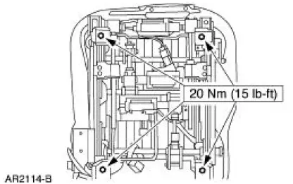
3. Remove the four seat track bolts.
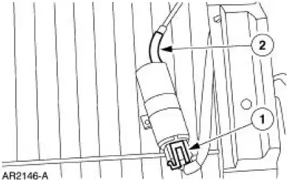
Vehicles with standard power lumbar
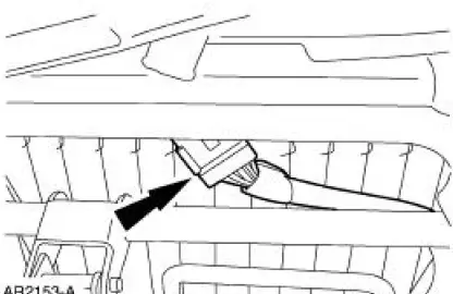
4. Release the J-clip.
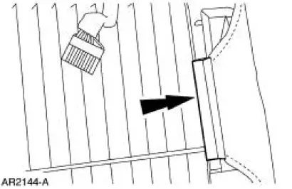
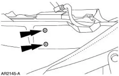
5. Remove the front seat backrest pad adjusting pump screws.
6. Remove the front seat backrest pad adjusting pump (65530).
1. Disconnect the electrical connector.
2. Disconnect the power lumbar support air hose.
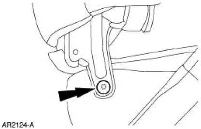
Vehicles with power bolster and lumbar
7. Remove the driver seat backrest latch. For additional information, refer to Latch-Front Seat Backrest in this section.
8. Remove the pivot bolt and seat backrest.
- Disconnect the power lumbar support air hoses.
9. Release the J-clips.
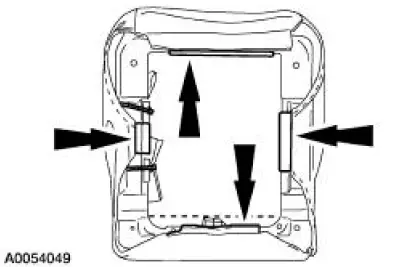
10. NOTE: When removing the cushion from the frame, it is not necessary to remove the trim cover from the cushion foam pad.
Remove the cushion foam pad from the frame.
11. NOTE: The lumbar and bolster pump and solenoid module is serviced as part of the cushion frame assembly.
Install a new seat cushion frame assembly.
All vehicles
12. To install, reverse the removal procedure.
 Seat Track
Removal and Installation
1. Remove the front seat. For additional information, refer to Seat-Front
Power in this section.
2. Remove the outboard seat trim shield.
3. Disconnect the electrical c ...
 Latch - Front Seat Backrest
Removal
NOTE: The power seat backrest adjuster assembly must be installed as a
new unit. Repair of the
power seat backrest adjuster assembly components is not acceptable and
should not be attemp ...
Other materials:
Differential Housing Cover
Removal
1. Raise and support the vehicle.
2. NOTE: Empty the lubricant into a clean container for reuse.
Remove the differential housing cover (4033).
1. Remove the 10 bolts and drain the lubricant from the differential
housing (4010).
2. Remove the d ...
Cylinder Head LH
Special Tool(s)
Remover, Power Steering
Pump Pulley
211-016 (T69L-10300-B)
Installer, Power Steering Pump
Pulley
211-009
Material
...
Fuel cut-off switch
WARNING: Failure to inspect and if necessary repair fuel leaks
after a collision may increase the risk of fire and serious injury.
Ford Motor Company recommends that the fuel system be inspected by
an authorized dealer after any collision.
In the event of a m ...
