Ford Mustang (1999-2004) Service Manual: Master Cylinder Priming - 4.6L
1. CAUTION: Use only bleed screws on the engine side of the brake master cylinder (2140). The hydro-boost bleed screw, located near the dash on the hydro-booster casting, is for the booster cavity filled with power steering fluid, not brake fluid.
Connect a clear waste line to the bleed screw closet to the booster first and the other end in a container partially filled with recommended brake fluid.
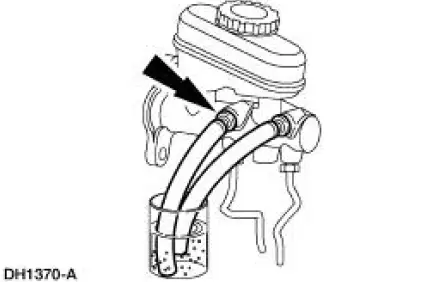
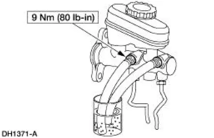
2. Open the bleeder screw, have an assistant push the brake pedal down slowly through full travel, close the bleeder screw, then return brake pedal slowly to full released position. Wait five seconds, then repeat operation until air bubbles cease to appear.
3. Repeat Step 2 for bleeder screw farthest from hydro-booster.
 Master Cylinder Priming - In-Vehicle or Bench
WARNING: Brake fluid contains polyglycol ethers and polyglycols. Avoid
contact with
eyes. Wash hands thoroughly after handling. If brake fluid contacts eyes, flush
eyes with
running water for 15 min ...
 Four Wheel Anti-Lock Brake System (4WABS) Hydraulic Control Unit (HCU)
NOTE: This procedure only needs to be performed if the 4-wheel
anti-lock brake (4WABS) hydraulic
control unit (HCU) has been installed new or if the HCU lines have been
opened.
1. Clean all ...
Other materials:
Mirror - Motor
Removal
1. Push in the upper edge of the mirror glass to the maximum travel.
2. Grasp the bottom of the mirror glass, pull outward and remove the mirror
glass.
3. Remove the mirror motor screws.
4. Disconnect the mirror motor electrical connector.
5. ...
Actuator Cable - Speed Control-Cobra
1. Remove the speed control actuator cable end from the throttle body.
1. Lift the speed control cable from the throttle nailhead.
2. Release the speed control cable from the throttle bracket.
2. Remove the speed control cable from the retaining cli ...
Battery and Cables
Vehicles are equipped with a 12 volt maintenance-free battery that
contains a built-in hydrometer. The
hydrometer eye indication is as follows:
A green dot means the battery is OK.
A yellow dot, red dot, or when the green dot is not visible,
...
