Ford Mustang (1999-2004) Service Manual: Module - Passive Anti-Theft Transceiver
Removal
1. CAUTION: Electronic modules are sensitive to electrical charges. If exposed to these charges, damage may result.
Disconnect the battery ground cable (14301).
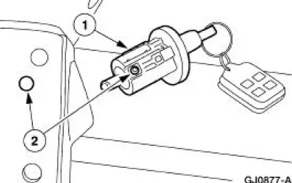
2. Remove the ignition switch lock cylinder (11582).
1. Insert the ignition key into the ignition switch lock cylinder and turn to the RUN position.
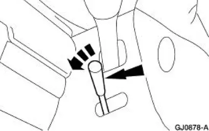
2. Insert a punch in the access hole of the steering column and press the release tab while pushing out the ignition switch lock cylinder.
3. Unscrew the tilt wheel handle and shank and remove.
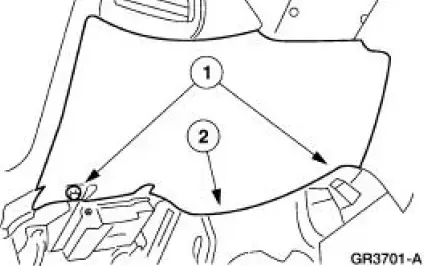
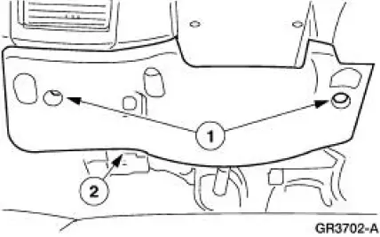
4. Remove the instrument panel steering column opening cover.
1. Remove the screws.
2. Remove the LH instrument panel steering column opening cover.
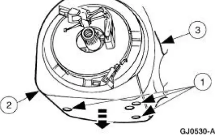
5. NOTE: The steering wheel has been removed for clarity.
Remove the upper and lower steering column shrouds.
1. Remove the screws.
2. Remove the lower steering column shroud.
3. Remove the upper steering column shroud.
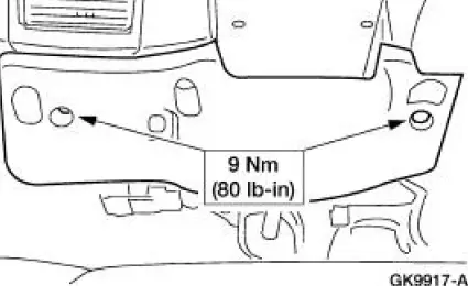
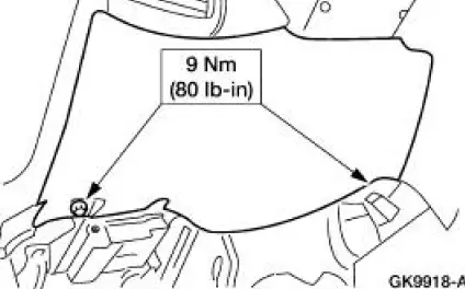
6. Remove the instrument panel steering column opening cover reinforcement.
1. Remove the bolts.
2. Remove the instrument panel steering column opening cover reinforcement.
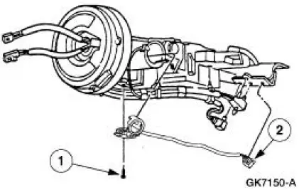
7. NOTE: The steering wheel has been removed for clarity.
Remove the anti-theft transceiver module.
1. Remove the screw from the bottom of the transceiver module.
2. NOTE: Only apply pressure or leverage below the key cylinder lower rib.
Disconnect the electrical connector and remove the module.
Installation
1. NOTE: When the is battery disconnected and reconnected, some abnormal drive symptoms may occur while the vehicle relearns its adaptive strategy. The vehicle may need to be driven 16 km (10 miles) or more to relearn the strategy.
To install, reverse the removal procedure.
 Security Access - Procedure
Special Tool(s)
Worldwide
418-F224,
New Generation STAR (NGS)
Tester
418-F052, or equivalent
diagnostic tool
NOTE: The security access procedure is utilized to obtain passive a ...
 Multifunction Electronic Control Modules
Torque Specifications
Module Controlled Functions
The generic electronic module (GEM)(14B205) is the only multifunction
control module on this vehicle.
The GEM controls the following function ...
Other materials:
Assembly
1. Inspect the clutch cylinder thrust surfaces, piston bore and clutch plate
serrations for scores or
burrs. Minor scores or burrs may be removed with crocus cloth. Install a new
clutch cylinder if
badly scored or damaged.
2. Check the fluid passage in the ...
Pinpoint Tests
PINPOINT TEST A: NO COMMUNICATION WITH THE INSTRUMENT
CLUSTER
Test Step
Result / Action to Take
A1 CHECK THE BATTERY POWER SUPPLY TO THE INSTRUMENT
CLUSTER
YesGO to A2 .
No
REPAIR the circuit.
TEST the system
for normal
operation.
...
Installation
WARNING: To reduce the risk of serious personal injury, read
and follow all warnings,
cautions and notes at the beginning of the removal procedure.
Vehicles receiving a new clockspring
1. NOTE: A new clockspring is supplied in a centralized position a ...
