Ford Mustang (1999-2004) Service Manual: Pinpoint Test L: B1892 - Air Bag Tone Warning Indicator Circuit Shorted to Ground or Open
Normal Operation
The restraints control module (RCM) monitors its connection to the generic electronic module (GEM) at C201e pin 10. This connection is used to signal a chime if the air bag indicator is inoperative and another SRS fault exists. If the RCM detects a short to ground or open on the connection to the GEM, it will store a diagnostic trouble code (DTC) B1892 in memory.
Possible Causes
An air bag tone warning indicator circuit short to ground or open can be caused by:
- a short to ground or open on circuit 1083 (LB/BK).
- a damaged or inoperative GEM.
PINPOINT TEST L: DTC B1892 - AIR BAG TONE WARNING INDICATOR CIRCUIT SHORTED TO GROUND OR OPEN
| Test Step | Result / Action to Take |
| L1 CHECK FOR A HARD OR INTERMITTENT DTC | Yes This is a hard fault. The fault condition is still present. This fault cannot be cleared until it is corrected and the DTC is no longer retrieved during the on-demand self test. GO to L2 . No This is an intermittent fault. The fault condition is not present at this time. GO to L5 . |
|
|
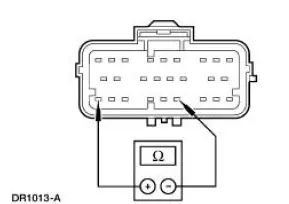
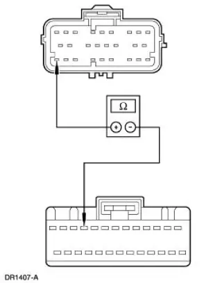
| L2 CHECK THE AIR BAG TONE WARNING INDICATOR CIRCUIT | Yes REPAIR the circuit. GO to L6 . No GO to L3 . |
| WARNING: If the supplemental restraint system
(SRS) is
being serviced, the system must be deactivated and restraint
system diagnostic tools must be installed. Refer to Air Bag
Supplemental Restraint System (SRS) in this section.
The air bag restraint system diagnostic tools must be removed and the air bag modules reconnected when the system is reactivated to avoid non-deployment in a collision, resulting in possible personal injury. NOTE: Diagnostics or repairs are not to be performed on a seat equipped with a seat side air bag with the seat in the vehicle. Prior to attempting to diagnose or repair a seat concern when equipped with a seat side air bag, the seat must be removed from the vehicle and the restraint system diagnostic tools must be installed in the seat side air bag electrical connectors. The restraint system diagnostic tools must be removed prior to operating the vehicle over the road. NOTE: After diagnosing or repairing an SRS, the restraint system diagnostic tools must be removed before operating the vehicle over the road. NOTE: After diagnosing or repairing a seat system, the restraint system diagnostic tools must be removed before operating the vehicle over the road. NOTE: The SRS must be fully operational and free of faults before releasing the vehicle to the customer.
|
|
| L3 CHECK THE AIR BAG TONE WARNING INDICATOR MODULE CIRCUIT | Yes REPAIR the circuit. GO to L6 . No GO to L4 . |
|
|
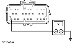
| L4 CHECK THE AIR BAG TONE WARNING INDICATOR | Yes INSTALL a new GEM. GO to L6 . No INSTALL a new RCM. GO to L6 . |
|
|
| L5 CHECK FOR AN INTERMITTENT FAULT | Yes CHECK for causes of intermittent short to ground or open on circuit 1083 (LB/BK). Attempt to recreate the hard fault by flexing the wire harness and cycling the ignition key frequently. REPAIR any intermittent concerns found. GO to L6 . No GO to L6 . |
|
|
| L6 CHECK FOR ADDITIONAL DTCs | Yes Do not clear any DTCs until all DTCs have been resolved. GO to the Restraints Control Module (RCM) Diagnostic Trouble Code (DTC) Priority Table in this section for pinpoint test direction. No RECONNECT the system. REACTIVATE the system. PROVE OUT the system. REFER to Air Bag Supplemental Restraint System (SRS) in this section. CLEAR all DTCs. |
|
 Pinpoint Test K: LFC 35/DTC B1935 - Passenger Air Bag Circuit Resistance
Low
Pinpoint Test K: LFC 35/DTC B1935 - Passenger Air Bag Circuit Resistance
Low
Normal Operation
The restraints control module (RCM) monitors the resistance of the
passenger air bag ignitor by
measuring the resistance between pins 6 and 7. If the RCM detects low
resistance ...
 Pinpoint Test M: DTC B1891 - Air Bag Tone Warning Indicator Circuit
Shorted to Battery or
Ignition
Pinpoint Test M: DTC B1891 - Air Bag Tone Warning Indicator Circuit
Shorted to Battery or
Ignition
Normal Operation
The restraints control module (RCM) monitors its connection to the
generic electronic module (GEM) at
pin 10. This connection is used to signal a chime if the air bag
indica ...
Other materials:
Gearshift Lever and Boot
Material
Removal and Installation
1. Remove the gearshift lever knob.
2. Remove the console panel gearshift plate. Lift the gearshift lever boot
over the gearshift lever.
3. Remove the bolts and the shift lever.
4. Remove the screws and the inner shif ...
Starter Motor - 4.6L
Removal
WARNING: When servicing starter motor (11002) or carrying out other
underhood work in
the vicinity of the starter motor, be aware that the heavy gauge battery
input lead at the starter
solenoid (11390) is "electrically hot" at all times. A prote ...
Sun visors
Slide-On-Rod
Rotate the visor toward the side
window and extend it rearward for
extra sunlight coverage.
Retract the visor before moving it
back toward the windshield and
storing it.
Illuminated Visor Vanity Mirror
Lift the cover to switch on the lamp.
Flex ...
