Ford Mustang (1999-2004) Service Manual: Pinpoint Tests
CAUTION: Before removing and installing the GEM or its connectors, disconnect the battery. Failure to follow this caution will result in the GEM storing many erroneous DTCs and it may exhibit erratic operation after installation.
CAUTION: Be careful when probing the central junction box (CJB), battery junction box (BJB) or any connectors. Damage will result to the connector receptacle if the probe being used is too large.
CAUTION: Electronic modules are sensitive to static electrical charges. If exposed to these charges, damage may result.
NOTE: If continuous DTCs are recorded and the symptom is not present when carrying out the pinpoint tests, an intermittent concern may be the cause. Always check for loose connections and corroded terminals.
NOTE: Complete the entire pinpoint test related to the symptom before installing a new GEM.
PINPOINT TEST A: NO COMMUNICATION WITH THE GENERIC ELECTRONIC MODULE (GEM)
| Test Step | Result / Action to Take |
| CAUTION: Use the correct probe adapter(s) when making measurements. Failure to use the correct probe adapter(s) may damage the connector. | |
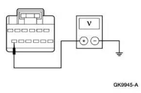
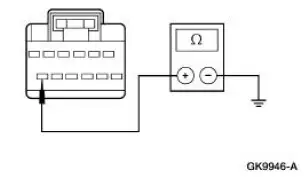
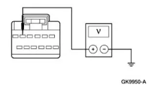
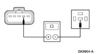
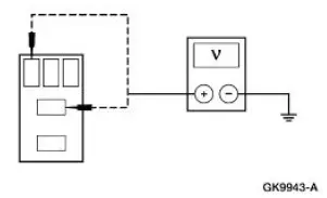
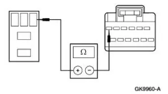
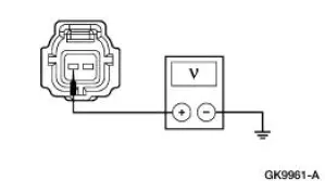
| A1 CHECK THE GENERIC ELECTRONIC MODULE (GEM) POWER SUPPLY | Yes GO to A2 . No REPAIR the circuit(s) in question. TEST the system for normal operation. |
|
|
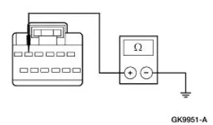
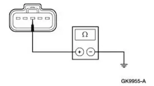
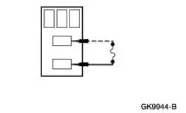
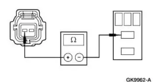
| A2 CHECK THE GEM GROUND CIRCUIT 397 (BK/WH) FOR OPEN | Yes GO to A3 . No REPAIR the cirucit(s) in question. TEST the system for normal operation. |
|
|
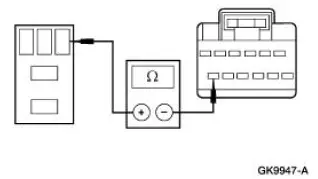
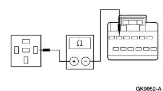
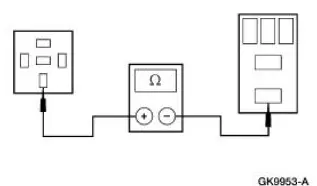
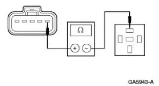
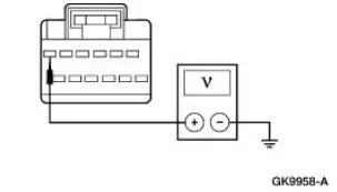
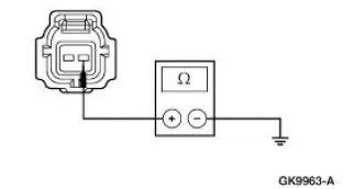
| A3 CHECK CIRCUIT 397 (BK/WH) FOR SHORT TO POWER | Yes REPAIR the circuit. TEST the system for normal operation. No REFER to Section |
|
|

PINPOINT TEST B: WINDSHIELD WIPERS DO NOT OPERATE / OPERATE CORRECTLY
| Test Step | Result / Action to Take |
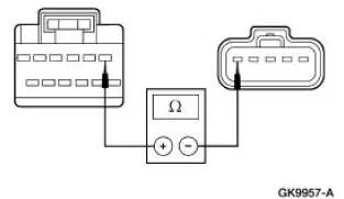
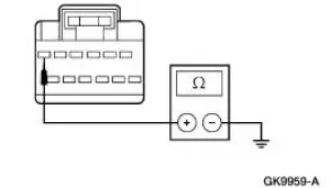
| B1 DETERMINE IF GEM IS RECEIVING CORRECT IGNITION SWITCH STATUS | Yes GO to B2 . No REFER to Section |
|
|
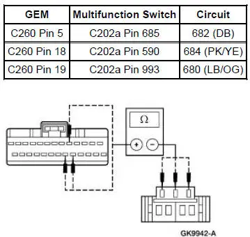
| B2 DETERMINE IF GEM IS RECEIVING CORRECT WIPER SWITCH STATUS FROM MULTIFUNCTION SWITCH | Yes GO to B3 . No GO to B6 |
|
|
| B3 TEST GEM CONTROL OF WIPER ON/OFF RELAY | Yes GO to B4 No GO to B10 |
|
|
| B4 TEST THE GEM CONTROL OF WIPER HIGH/LOW RELAY | Yes GO to B5 . No GO to B16 . |
|
|
| B5 DETERMINE IF GEM IS RECEIVING CORRECT WIPER POSITION STATUS | Yes INSTALL a new GEM. For additional information, REFER to Section. CLEAR the DTCs. REPEAT the self-test. No GO to B27 . |
|
|
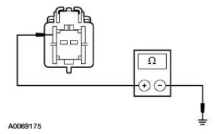
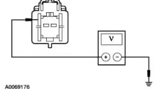
| B6 TEST THE MULTIFUNCTION SWITCH FOR NORMAL OPERATION | Yes GO to B7 . No INSTALL a new multifunction switch; REFER to Section . REPEAT the selftest. CLEAR the DTCs |
|
|
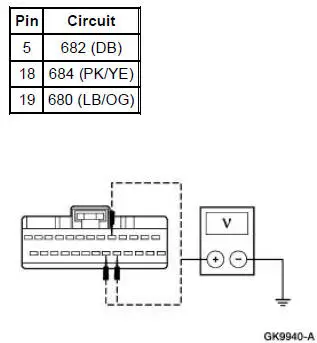
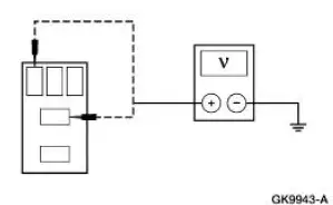
| B7 CHECK CIRCUITS 682 (DB), 684 (PK/YE), AND 680 (LB/OG) FOR SHORT TO BATTERY BETWEEN THE GEM AND THE MULTIFUNCTION SWITCH | Yes REPAIR the circuit(s) in question. REPEAT the selftest. CLEAR the DTCs. No GO to B8 . |
|
|
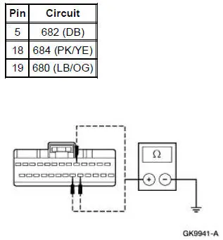
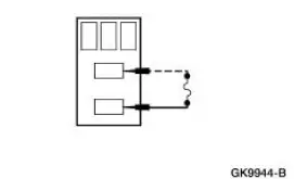
| B8 CHECK CIRCUITS 682 (DB), 684 (PK/YE), AND 680 (LB/OG) FOR SHORT TO GROUND BETWEEN THE GEM AND THE MULTIFUNCTION SWITCH | Yes REPAIR the circuit(s) in question. REPEAT the selftest. CLEAR the DTCs. No GO to B9 . |
|
|
| B9 CHECK CIRCUITS 682 (DB), 684 (PK/YE), AND 680 (LB/OG) FOR AN OPEN CONDITION BETWEEN GEM AND MULTIFUNCTION SWITCH | Yes INSTALL a new GEM. For additional information, REFER to Section. REPEAT the self-test. CLEAR the DTCs. No REPAIR circuit(s) in question. REPEAT the self-test. CLEAR the DTCs. |
|
|
| B10 CHECK CIRCUITS 65 (DG) FOR OPEN CIRCUIT CONDITION BETWEEN BJB AND CJB | Yes GO to B11 . No REPAIR circuit(s) in question. REPEAT the self-test. CLEAR the DTCs. |
NOTE: Verify voltage at CJB F26 (30A) before carrying out this test.
|
|
| B11 ISOLATE PROBLEM BETWEEN GEM AND BJB | Yes GO to B12 . No GO to B22 . |
|
|
| B12 CARRY OUT THE WIPER ON/OFF RELAY COMPONENT TEST | Yes GO to B13 . No INSTALL a new wiper ON/OFF relay. REPEAT the self-test. CLEAR the DTCs |
|
|
| B13 CHECK CIRCUIT 646 (YE/WH) FOR SHORT TO BATTERY BETWEEN GEM AND BJB | Yes REPAIR Circuit 646 (YE/WH). REPEAT the selftest. CLEAR the DTCs. No GO to B14 . |
|
|
| B14 CHECK CIRCUIT 646 (YE/WH) FOR SHORT TO GROUND BETWEEN GEM AND BJB | Yes GO to B15 . No REPAIR Circuit 646 (YE/WH). REPEAT the selftest. CLEAR the DTCs. |
|
|
| B15 CHECK CIRCUIT 646 (YE/WH) FOR OPEN BETWEEN GEM AND BJB | Yes INSTALL a new GEM. For additional information REFER to Section. REPEAT the self-test. CLEAR the DTCs. No REPAIR Circuit 646 (YE/WH). REPEAT the selftest. CLEAR the DTCs. |
|
|
| B16 CHECK CIRCUITS 65 (DG) AND 61 (YE/RD) FOR OPEN CONDITION BETWEEN BJB AND CJB | Yes GO to B17 . No REPAIR circuit in question. REPEAT the self-test. CLEAR the DTCs. |
|
|
| B17 ISOLATE THE PROBLEM BETWEEN THE GEM AND THE BJB | Yes GO to B18 . No GO to B26 . |
|
|
| B18 CARRY OUT COMPONENT TEST ON WIPER HIGH/LOW RELAY | Yes GO to B19 . No INSTALL a new wiper HIGH/LOW relay. REPEAT the self-test. CLEAR the DTCs. |
|
|
| B19 CHECK CIRCUIT 647 (GY/LB) FOR SHORT TO BATTERY BETWEEN GEM AND BJB | Yes REPAIR Circuit 647 (GY/LB). REPEAT the self-test. CLEAR the DTCs. No GO to B20 . |
|
|
| B20 CHECK CIRCUIT 647 (GY/LB) FOR SHORT TO GROUND BETWEEN GEM AND BJB | Yes GO to B21 . No REPAIR Circuit 647 (GY/LB). REPEAT the self-test. CLEAR the DTCs. |
|
|
| B21 CHECK CIRCUIT 647 (GY/LB) FOR OPEN CONDITION BETWEEN GEM AND BJB | Yes INSTALL a new GEM. REFER to Section. REPEAT the self-test. CLEAR the DTCs. No REPAIR Circuit 647 (GY/LB). REPEAT the self-test. CLEAR the DTCs. |
|
|
| B22 CHECK CIRCUIT 61 (YE/RD) FOR OPEN CIRCUIT CONDITION BETWEEN WIPER ON/OFF AND HIGH/LOW RELAYS | Yes GO to B23 . No REPAIR Circuit 61 (YE/RD). REPEAT the self-test. CLEAR the DTCs. |
|
|
| B23 CARRY OUT THE WIPER HIGH/LOW RELAY COMPONENT TEST | Yes GO to B24 . No INSTALL a new wiper HIGH/LOW relay. REPEAT the self-test. CLEAR the DTCs. |
|
|
| B24 CHECK CIRCUIT 56 (DB/OG) FOR AN OPEN CIRCUIT BETWEEN THE WIPER HIGH/LOW RELAY AND THE WIPER MOTOR | Yes GO to B25 . No REPAIR Circuit 56 (DB/OG). REPEAT the self-test. CLEAR the DTCs. |
|
|
| B25 CHECK CIRCUIT 1205 (BK) FOR OPEN CIRCUIT CONDITION BETWEEN WIPER MOTOR AND GROUND | Yes CARRY OUT the windshield wiper motor component test. REFER to Component Test. If the component fails, INSTALL a new wiper motor; REFER to Motor-Windshield Wiper . REPEAT the self-test. CLEAR the DTCs. No REPAIR Circuit 1205 (BK). REPEAT the self-test. CLEAR the DTCs. |
|
|
| B26 CHECK CIRCUIT 58 (WH) FOR AN OPEN CIRCUIT BETWEEN THE WIPER HIGH/LOW RELAY AND THE WIPER MOTOR | Yes CARRY OUT the windshield wiper motor component test. REFER to Component Test. If the component fails, INSTALL a new wiper motor; REFER to Motor-Windshield Wiper . REPEAT the self-test. CLEAR the DTCs. No REPAIR Circuit 58 (WH). REPEAT the self-test. CLEAR the DTCs. |
|
|
| B27 CHECK CIRCUIT 28 (BK/PK) FOR OPEN CIRCUIT CONDITION BETWEEN THE WIPER HIGH/LOW RELAY AND THE WIPER MOTOR | Yes INSTALL a new wiper motor; REFER to Motor-Windshield Wiper . REPEAT the self-test. CLEAR the DTCs. No REPAIR Circuit 28 (BK/PK). REPEAT the self-test. CLEAR the DTCs. |
|
PINPOINT TEST C: WINDSHIELD WASHERS DO NOT OPERATE / OPERATE CORRECTLY
| Test Step | Result / Action to Take |
| C1 DETERMINE IF GEM IS RECEIVING CORRECT IGNITION SWITCH STATUS | Yes GO to C2 . No REFER to Section |
|
|
| C2 DETERMINE IF GEM IS RECEIVING CORRECT WIPER SWITCH STATUS FROM MULTIFUNCTION SWITCH | Yes GO to C3 . No GO to Pinpoint Test B . |
|
|
| C3 CHECK GEM CONTROL OF THE WASHER ON/OFF RELAY | Yes INSTALL a new GEM; REFER to Section . REPEAT the self-test. CLEAR the DTCs. No GO to C4 . |
|
|
| C4 CHECK CIRCUIT 65 (DG) FOR OPEN CIRCUIT BETWEEN CJB AND WASHER ON/OFF RELAY | Yes GO to C5 . No REPAIR the circuit in question. REPEAT the self-test. CLEAR the DTCs. |
NOTE: Verify voltage at CJB F26 (30A) before carrying out this test.
|
|
| C5 ISOLATE THE PROBLEM BETWEEN GEM AND BJB | Yes GO to C6 . No GO to C10 |
|
|
| C6 CARRY OUT WASHER ON/OFF RELAY COMPONENT TEST | Yes GO to C7 . No INSTALL a new wiper ON/OFF relay. REPEAT the self-test. CLEAR the DTCs. |
|
|
| C7 CHECK CIRCUIT 686 (TN/RD) FOR SHORT TO BATTERY BETWEEN GEM AND BJB | Yes REPAIR Circuit 686 (TN/RD). REPEAT the self-test. CLEAR the DTCs. No GO to C8 |
|
|
| C8 CHECK CIRCUIT 686 (TN/RD) FOR SHORT TO GROUND BETWEEN GEM AND BJB | Yes GO to C9 . No REPAIR Circuit 686 (TN/RD). REPEAT the self-test. CLEAR the DTCs. |
|
|
| C9 CHECK CIRCUIT 686 (TN/RD) FOR AN OPEN CIRCUIT BETWEEN GEM AND WASHER ON/OFF RELAY | Yes INSTALL a new GEM; REFER to Section . REPEAT the self-test. CLEAR the DTCs. No REPAIR Circuit 686 (TN/RD). REPEAT the self-test. CLEAR the DTCs. |
|
|
| C10 CHECK CIRCUIT 941 (BK/WH) FOR SHORT TO BATTERY BETWEEN BJB AND WASHER MOTOR | Yes REPAIR Circuit 941 (BK/WH). REPEAT the self-test. CLEAR the DTCs. No GO to C11 . |
|
|
| C11 CHECK CIRCUIT 941 (BK/WH)FOR OPEN BETWEEN THE BJB AND THE WASHER MOTOR | Yes GO to C12 . No REPAIR Circuit 941 (BK/WH). REPEAT the self-test. CLEAR the DTCs. |
|
|
| C12 CHECK CIRCUIT 1205 (BK) FOR AN OPEN | Yes INSTALL a new washer motor. REPEAT the self-test. CLEAR the DTCs. No REPAIR Circuit 1205 (BK). REPEAT the self-test. CLEAR the DTCs. |
|
 Inspection and Verification
1. Verify the customer concern by operating the wiper/washer system.
2. Visually inspect for obvious signs of mechanical and electrical
damage.
Visual Inspection Chart
Mechanical
Electr ...
 Component Test
Windshield Wiper Motor
CAUTION: Do not handle the wiper motor abusively when
diagnosing the wiper
operations. Failure to follow this caution may result in damage to the
motor magnets and wil ...
Other materials:
Principles of Operation
Multifunction Wipers
The front wiper/washer feature controls the speed of the front
windshield wipers and the amount of
washer fluid sprayed on the front windshield when requested by the
customer. There are five (5) wiper
modes: OFF, LOW, HIGH, INT ...
Automatic Transaxle/Transmission
General Specifications
a - MERCON V is not interchangeable at this time with the current MERCON
fluids. Check the
transmission fluid level indicator to determine the correct fluid and refer to
the Workshop/Owner
publication to determine the correct service ...
Compressor Manifold and Tube Assembly - 4.6L
Material
Item
Specification
PAG Refrigerant Compressor
Oil (R-134a Systems)
F7AZ-19589-DA (Motorcraft YN-
12-C)
WSH-M1C231-
B
Removal and Installation
NOTE: Installation of a new suction accumulator is not required when
repairing the ...
