Ford Mustang (1999-2004) Service Manual: Compressor Manifold and Tube Assembly - 4.6L
Material
| Item | Specification |
| PAG Refrigerant Compressor Oil (R-134a Systems) F7AZ-19589-DA (Motorcraft YN- 12-C) | WSH-M1C231- B |
Removal and Installation
NOTE: Installation of a new suction accumulator is not required when repairing the air conditioning system except when there is physical evidence of contamination from a failed A/C compressor or damage to the suction accumulator.
1. Recover the refrigerant. For additional information, refer to Section.
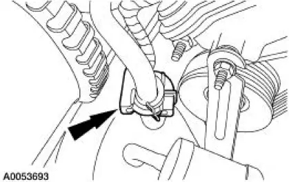
2. Disconnect the suction line spring lock coupling.
- Discard the O-ring seals.
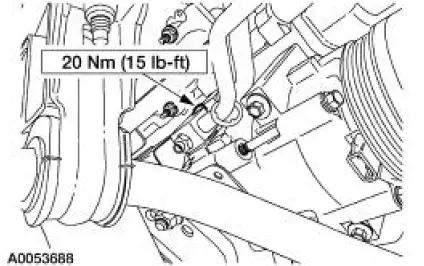
3. Remove the A/C muffler bracket nut.
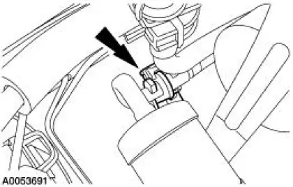
4. Disconnect the spring lock coupling.
- Discard the O-ring seals.
5. Raise the vehicle. For additional information, refer to Section.
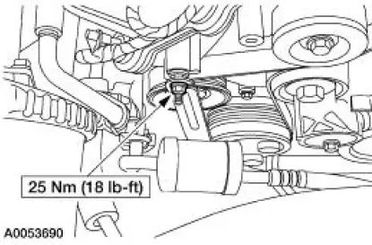
6. Remove the bolt and the compressor manifold assembly.
- Discard the O-ring seals.
7. To install, reverse the removal procedure.
- Install new O-ring seals lubricated in clean PAG oil.
- Lubricate the refrigerant system with the correct amount of clean PAG oil. For additional information, refer to Section.
8. Evacuate, leak test and charge the refrigerant system. For additional information, refer to Section.
 Compressor Manifold and Tube Assembly - 3.8L
Material
Item
Specification
PAG Refrigerant Compressor
Oil (R-134a Systems)
F7AZ-19589-DA (Motorcraft YN-
12-C)
WSH-M1C231-
B
Removal and Installation
NOTE: Installation of a ...
 Suction Accumulator to Compressor Line - 4.6L
Material
Item
Specification
PAG Refrigerant Compressor
Oil (R-134a Systems)
F7AZ-19589-DA (Motorcraft YN-
12-C)
WSH-M1C231-
B
Removal and Installation
NOTE: Installation of a ...
Other materials:
Technical specifications
Wheel Lug Nut Torque Specifications
WARNING: When a wheel is installed, always remove any
corrosion, dirt or foreign materials present on the mounting
surfaces of the wheel or the surface of the wheel hub, brake drum or
brake disc that contacts the wheel. Make ...
Switch - Horn
Removal
1. Remove the driver side air bag module (043B13). Refer to Section.
2. Remove the switches.
1. Disconnect the horn wire from the switches.
2. Remove the horn switch screws and remove the switches.
Installation
1. To install, reve ...
Clutch Controls (Description and Operation)
The clutch control system engages and disengages the clutch. The clutch
control system disengages
the clutch when the clutch pedal is depressed and engages the clutch when the
clutch pedal is
released. Clutch pedal motion is transmitted by the c ...
