Ford Mustang (1999-2004) Service Manual: Rear View Mirrors (Diagnosis and Testing)
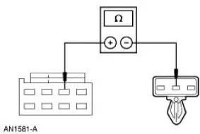
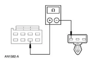
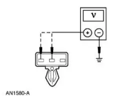
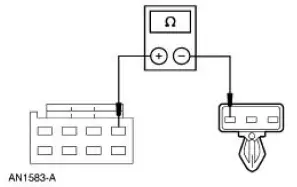
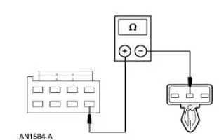
Refer to Wiring Diagrams Cell 124 , Power Mirrors for schematic and connector information.
Special Tool(s)
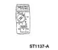 |
73III Automotive Meter 105-R0057 or equivalent |
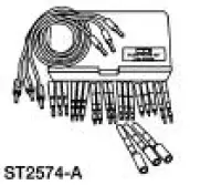 |
Flex Probe Kit 105-R025B or equivalent |
Inspection and Verification
1. Verify the customer concern by operating the system.
2. Visually inspect for obvious signs of mechanical or electrical damage.
Visual Inspection Chart
| Mechanical | Electrical |
|
|
3. If an obvious cause for an observed or reported concern is found, correct the cause (if possible) before proceeding to the next step.
4. If the concern is not visually evident, verify the symptom and refer to the Symptom Chart.
Symptom Chart
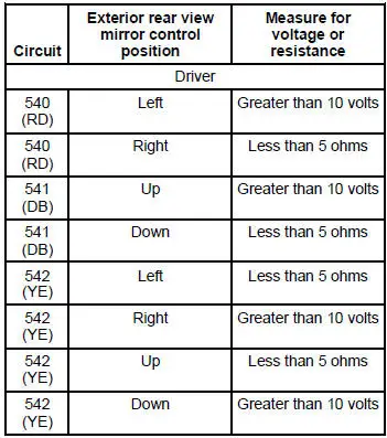
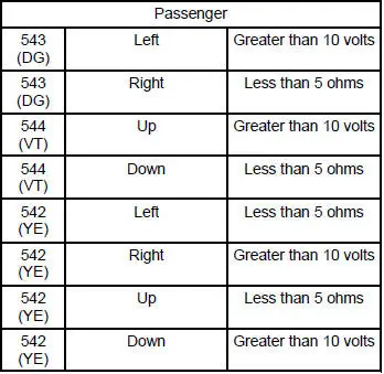
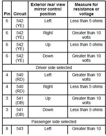
Refer to the Wiring Diagrams for connector numbers stated in the pinpoint tests.
| Condition | Possible Sources | Action |
|
|
|
|
|
|
|
|
|
Pinpoint Tests
PINPOINT TEST A: THE MIRRORS ARE INOPERATIVE
| Test Step | Result / Action to Take |
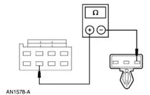
| A1 CHECK CIRCUIT 326 (WH/VT) | Yes GO to A2 . No REPAIR the circuit. TEST the system for normal operation. |
|
|
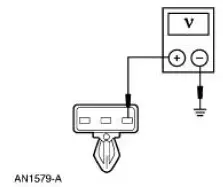
| A2 CHECK CIRCUIT 1205 (BK) FOR AN OPEN | Yes GO to A3 . No REPAIR the circuit. TEST the system for normal operation. |
|
|
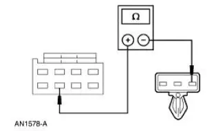
| A3 CHECK CIRCUIT 542 (YE) FOR AN OPEN | Yes INSTALL a new exterior rear view mirror control. REFER to Switch- Exterior Rear View Mirror Control in this section. No REPAIR the circuit. TEST the system for normal operation. |
|
PINPOINT TEST B: A SINGLE MIRROR IS INOPERATIVE
| Test Step | Result / Action to Take |
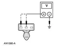
| B1 CHECK THE COMMON FEED INPUT | Yes GO to B3 . No GO to B2 . |
|
|
| B2 CHECK CIRCUIT 542 (YE) FOR AN OPEN | Yes INSTALL a new exterior rear view mirror control. REFER to Switch- Exterior Rear View Mirror Control in this section. TEST the system for normal operation. No REPAIR the circuit. TEST the system for normal operation. |
|
|
| B3 CHECK THE UP/DOWN INPUT | Yes GO to B6 . No GO to B4 for driver inoperative or GO to B5 for passenger inoperative. |
|
|
| B4 CHECK CIRCUIT 541 (DB) FOR AN OPEN | Yes INSTALL a new exterior rear view mirror control. REFER to Switch- Exterior Rear View Mirror Control in this section. TEST the system for normal operation. No REPAIR the circuit. TEST the system for normal operation. |
|
|
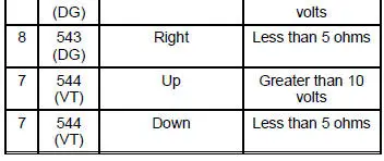
| B5 CHECK CIRCUIT 544 (VT) FOR AN OPEN | Yes INSTALL a new exterior rear view mirror control. REFER to Switch- Exterior Rear View Mirror Control in this section. TEST the system for normal operation. No REPAIR the circuit. TEST the system for normal operation. |
|
|
| B6 CHECK THE LEFT/RIGHT INPUT | Yes INSTALL a new exterior rear view mirror motor. REFER to Mirror-Motor in this section. TEST the system for normal operation. No GO to B7 for driver inoperative or GO to B8 for passenger inoperative. |
|
|
| B7 CHECK CIRCUIT 540 (RD) FOR AN OPEN | Yes INSTALL a new exterior rear view mirror control. REFER to Switch- Exterior Rear View Mirror Control in this section. TEST the system for normal operation. No REPAIR the circuit. TEST the system for normal operation. |
|
|
| B8 CHECK CIRCUIT 543 (DG) FOR AN OPEN | Yes INSTALL a new exterior rear view mirror control. REFER to Switch- Exterior Rear View Mirror Control in this section. TEST the system for normal operation. No REPAIR the circuit. TEST the system for normal operation. |
|
PINPOINT TEST C: A SINGLE MIRROR DOES NOT FUNCTION WITH SWITCH LOGIC
| Test Step | Result / Action to Take |
| C1 CHECK THE EXTERIOR REAR VIEW MIRROR LOGIC | Yes INSTALL a new exterior rear view mirror motor. REFER to Mirror-Motor in this section. TEST the system for normal operation. No GO to C2 . |
|
|
| C2 CHECK THE EXTERIOR REAR VIEW MIRROR CONTROL | Yes REPAIR the circuits. TEST the system for normal operation. No INSTALL a new exterior rear view mirror control. REFER to Switch-Exterior Rear View Mirror Control in this section. TEST the system for normal operation. |
|
Mirror - Power Exterior Rear View
Removal
1. Remove the door trim panel. For additional information, refer to Section.
2. Disconnect the power exterior rear view mirror electrical connector.
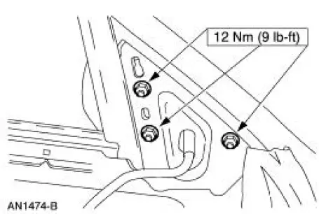
3. Remove the nuts and the power exterior rear view mirror.
Installation
1. To install, reverse the removal procedure.
 Rear View Mirrors
Torque Specifications
Rear View Mirrors
The rear view mirror system consists of the following components:
exterior rear view mirror
exterior rear view mirror control
exterior rear view ...
 Mirror - Motor
Removal
1. Push in the upper edge of the mirror glass to the maximum travel.
2. Grasp the bottom of the mirror glass, pull outward and remove the mirror
glass.
3. Remove the mirror motor screws.
...
Other materials:
Engine Ignition (Description and Operation)
Eight separate ignition coils:
are controlled by the powertrain control module (PCM).
are mounted directly above each spark plug.
are controlled by the powertrain control module for correct firing
sequence.
The spark plug:
changes the high vo ...
Output Shaft
Special Tool(s)
Pinion Bearing Cone Remove
205-D002 (D79L-4621-A) or
Equivalent
Spiral Snap Ring Replacer
308-096 (T85P-7025-A)
Disassembly
1. Using the special tool and a press, remove the third/fourth gear
synchronizer asse ...
General information on radio frequencies
This device complies with part 15 of the FCC Rules and with Industry
Canada license-exempt RSS standard(s). Operation is subject to the
following two conditions: (1) This device may not cause harmful
interference, and (2) This device must accept any interferen ...
