Ford Mustang (1999-2004) Service Manual: Removal
CAUTION: Electronic modules are sensitive to static electrical charges. If exposed to these charges, damage may result.
1. Remove the driver air bag module. For additional information, refer to Section.
2. Remove the passenger air bag module. For additional information, refer to Sectio.
3. Remove the LH front wheel and tire assembly. For additional information, refer to Section.
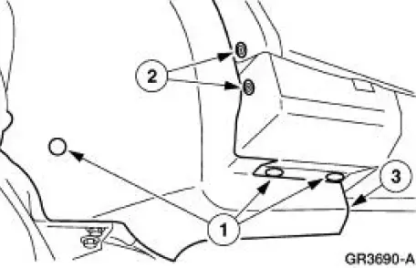
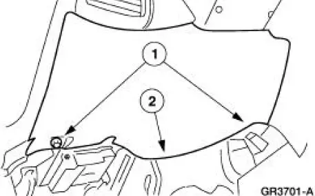
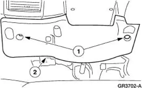
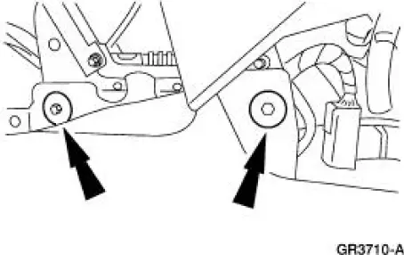
4. Position the LH fender splash shield away from the dash panel.
1. Remove the pin-type retainers.
2. Remove the screws.
3. Position the LH fender splash shield away from the dash panel.
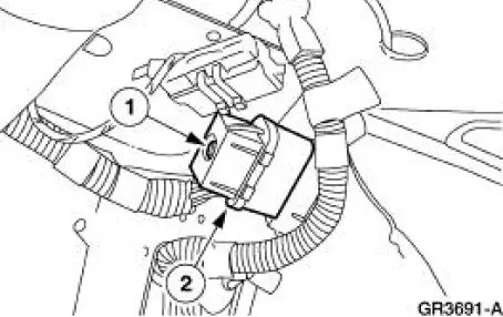
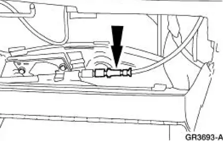
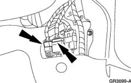
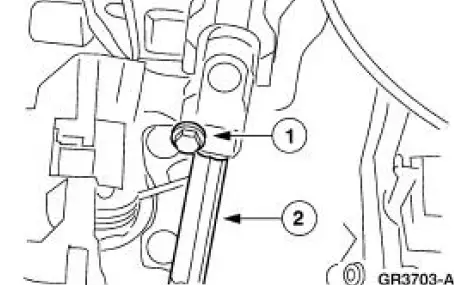
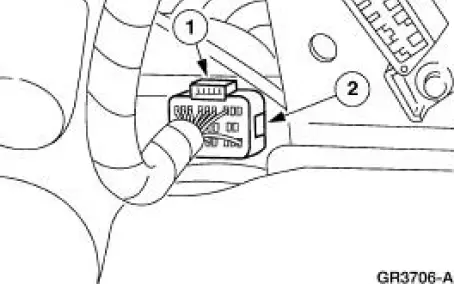
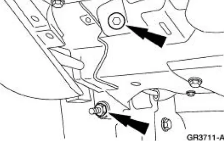
5. Disconnect the bulkhead electrical connector from inside the fender opening.
1. Loosen the bolt.
2. Disconnect the bulkhead electrical connector.
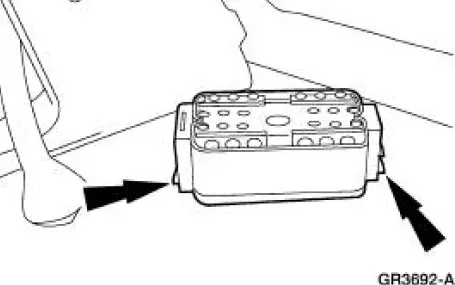
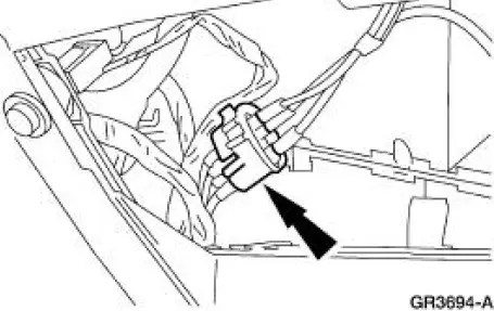
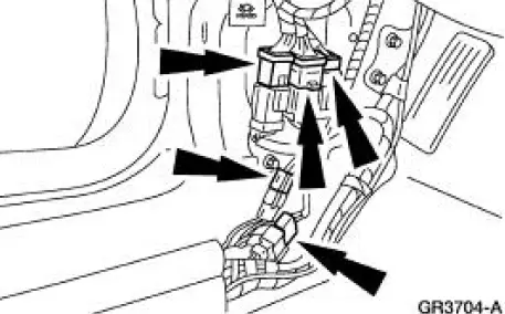
6. Release the bulkhead electrical connector from the dash panel.
7. Install the LH front wheel and tire assembly. For additional information, refer to Section.
8. Remove the floor console. For additional information, refer to Floor Console in this section.
9. Remove the upper RH instrument panel support bolt.
10. Disconnect the antenna in-line connector.
11. Disconnect the climate control vacuum harness connector.
12. Close the glove compartment.
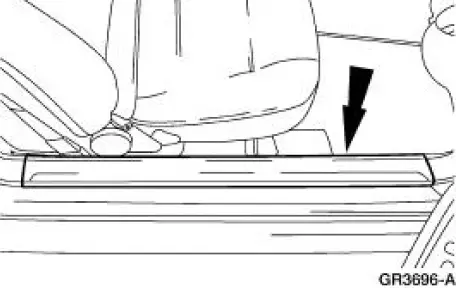
13. Remove the LH and RH scuff plates.
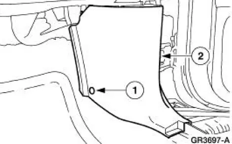
14. Remove the LH and RH A-pillar lower trim panels.
1. Remove the pin-type retainers.
2. Remove the A-pillar lower trim panels.
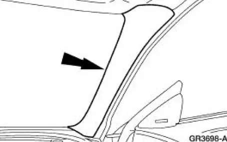
15. Remove the LH and RH windshield side garnish mouldings.
- If equipped with a convertible top, remove the pin-type retainers.
16. Position the LH and RH door weatherstrips aside.
17. Disconnect the RH main wiring harness electrical connectors.
18. Disconnect the climate control wiring harness connector.
19. Remove the instrument panel steering column cover.
1. Remove the screws.
2. Remove the instrument panel steering column cover.
20. Remove the instrument panel reinforcement.
1. Remove the screws.
2. Remove the instrument panel reinforcement.
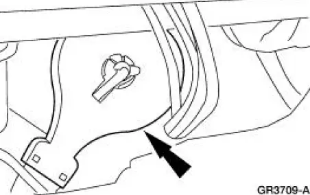
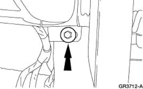
21. Separate the intermediate shaft from the steering column shaft.
1. Remove the pinch bolt.
2. Separate the intermediate shaft from the steering column shaft.
22. NOTE: The corner of the carpet may have to be pulled back slightly to carry out this step.
Disconnect the LH main wiring harness electrical connectors.
23. Disconnect the generic electronic module (GEM) electrical connectors.
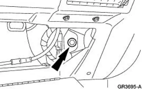
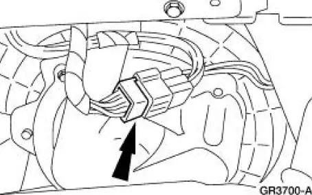
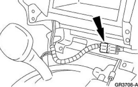
24. Disconnect the electronic crash sensor (ECS) module electrical connector.
1. Release the locking tab.
2. Disconnect the ECS module electrical connector.
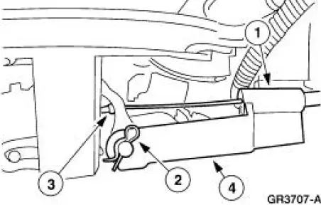
25. If equipped, disconnect the shift interlock assembly from the selector lever.
1. Remove the screw.
2. Remove the R-clip.
3. Disconnect the shift interlock cable.
4. Disconnect the shift interlock assembly from the selector lever.
26. Remove the audio unit. For additional information, refer to Section.
27. If equipped, disconnect the shifter assembly electrical connector.
28. NOTE: This step is being carried out through the audio unit opening.
NOTE: Rotate the temperature control switch to the cool position.
Release the temperature control cable from the blend door.
29. Remove the four center instrument panel support bolts.
30. Remove the LH instrument panel support bolt and nut.
31. Remove the RH instrument panel support bolt.
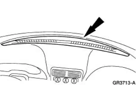
32. Remove the instrument panel defroster grille.
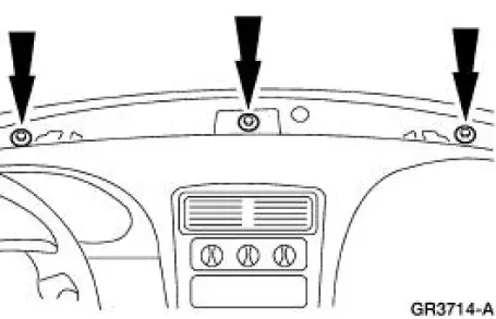
33. Remove upper instrument panel support bolts.
34. NOTE: Two technicians are necessary to carry out this step.
Remove the instrument panel.

 Installation
CAUTION: Electronic modules are sensitive to static electrical
charges. If exposed to
these charges, damage may result.
1. NOTE: Two technicians are necessary to carry out this step.
Install ...
Other materials:
Changing the vehicle battery
WARNING: Batteries normally produce explosive gases which
can cause personal injury. Therefore, do not allow flames, sparks
or lighted substances to come near the battery. When working near the
battery, always shield your face and protect your eyes. Always pro ...
Brake Disc Machining
Special Tool(s)
Gauge, Clutch Housing
308-021 (T75L-4201-A)
Dial Indicator Gauge with
Holding Fixture
100-002 (TOOL-4201-C) or
equivalent
Material
Item
Specification
Metal Surface Cleaner
F4AZ-19A536-RA or equiv ...
Fuel Pressure Sensor
Material
Item
Specification
Super Premium SAE 5W-20
Motor Oil
XO-5W20-DSP or equivalent
WSS-M2C914-
A
Removal
WARNING: Do not smoke or carry lighted tobacco or open flame of
any type when
working on or near any fuel related compo ...
