Ford Mustang (1999-2004) Service Manual: Removal
1. Remove the differential assembly from the differential housing. For additional information, refer to Differential Case in this section.
2. CAUTION: Record the torque necessary to maintain rotation of the drive pinion gear through several revolutions prior to removing the pinion flange (4851).
Remove the pinion flange. For additional information, refer to Drive Pinion Flange and Drive Pinion Seal in this section.
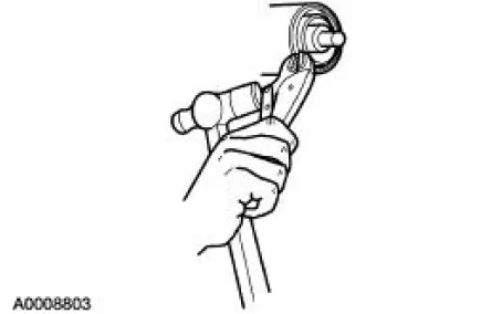
3. Force the rear axle drive pinion seal metal flange up. Install gripping pliers and strike with a hammer to remove the seal.
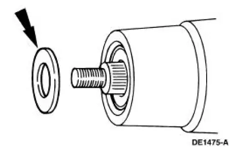
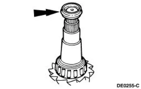
4. Remove the rear axle drive pinion shaft oil slinger (4670).
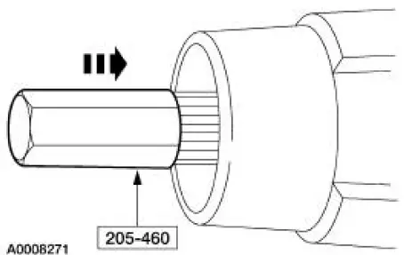
5. Using the special tool and a soft-faced hammer, drive the pinion assembly out of the outer differential pinion bearing (4621) and remove the drive pinion through the rear of the differential housing (4010).
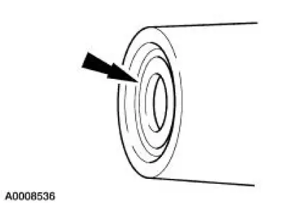
6. Remove the outer differential pinion bearing.
7. Remove and discard the collapsible spacer (4662).
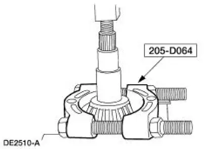
8. Using the special tool and a suitable press, remove the inner differential pinion bearing (4630).
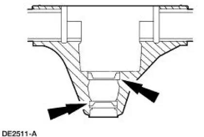
9. NOTE: Do not remove the pinion bearing cups from the differential housing unless the cups are damaged.
To remove the bearing cups, tap alternately (with a brass drift of suitable length) on opposite sides of the cup to prevent the cup from cocking in the casting.
 Drive Pinion
Special Tool(s)
Adapter for 205-S127
205-105 (T76P-4020-A3)
Adapter for 205-S127
205-109 (T76P-4020-A9)
Adapter for 205-S127
205-110 (T76P-4020-A10)
Adapter fo ...
 Installation
Using special tool 205-054
NOTE: This is the preferred method for installing the pinion bearing
cups. If necessary, proceed to
Using special tools 205-153, 205-054, and 205-D055 in this procedure for ...
Other materials:
Accelerator Pedal and Shaft
Removal and Installation
1. Push the accelerator cable nylon bushing out of the accelerator pedal and
shaft arm.
2. Remove the accelerator pedal and shaft.
Remove the nuts.
Remove the accelerator pedal and shaft.
3. To install, reverse the removal pro ...
Under hood overview
3.7L V6 Engine
A. Battery
B. Engine oil dipstick
C. Engine oil filler cap
D. Brake fluid reservoir
E. Air filter assembly
F. Engine coolant reservoir
G. Windshield washer fluid reservoir
H. Power distribution box
5.0L V8 Engine
A. Battery
B. Engine oil fille ...
Inspection and Verification
CAUTION: Do not hold the steering wheel (3600) at the stops for an
extended amount of
time. Damage to the power steering pump (3A674) will result.
NOTE: Make the following preliminary checks before repairing the
steering system:
1. Verify the customer conce ...
