Ford Mustang (1999-2004) Service Manual: Installation
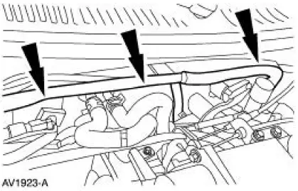
1. Position the fuel charging wiring in the vehicle and attach to the rear of the intake manifold.
2. NOTE: Make sure the locking clips are fully engaged into the bracket.
Reposition the accelerator cable and the speed control cable (if equipped) and install the cables into the bracket.
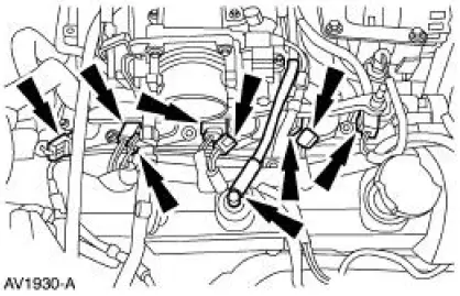
3. Connect the vacuum lines.
4. Connect the main vacuum hose.
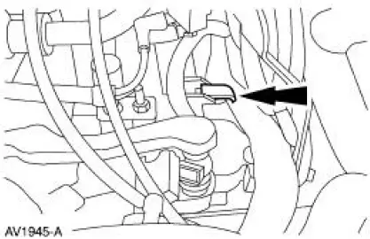
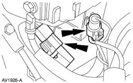
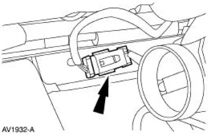
5. Connect the two connectors.
6. Install the battery supply wire, tighten the nut and close the cover.
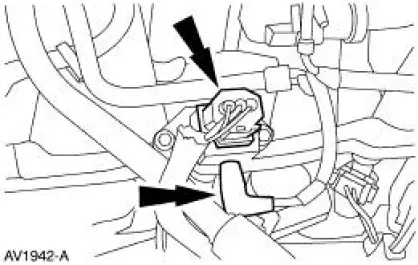
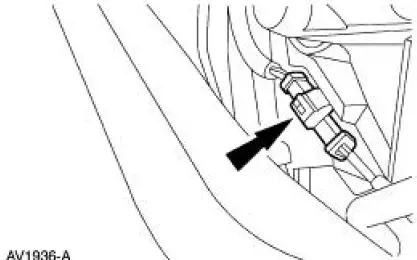
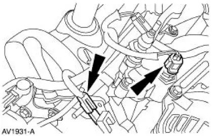
7. Connect the fuel pressure sensor and the vacuum hose.
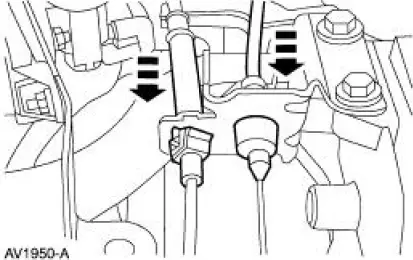
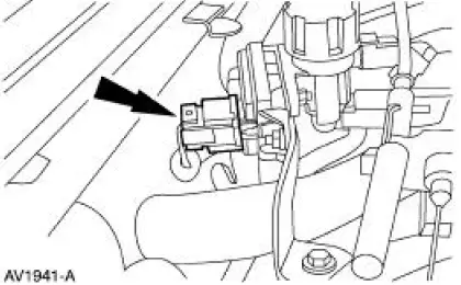
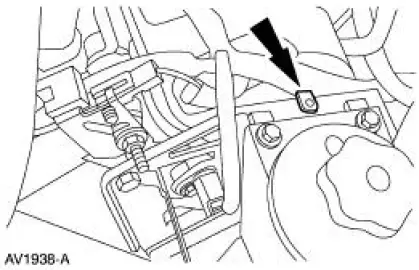
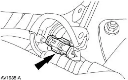
8. Connect the EGR pressure transducer electrical connector.
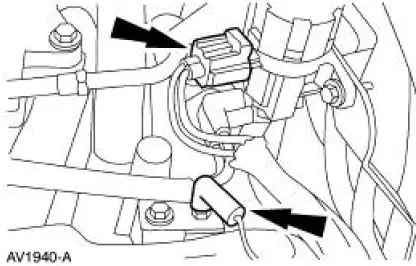
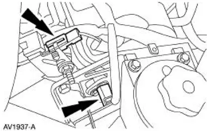
9. Connect the following connectors:
- Ground wire
- Exhaust vacuum regulator (EVR)
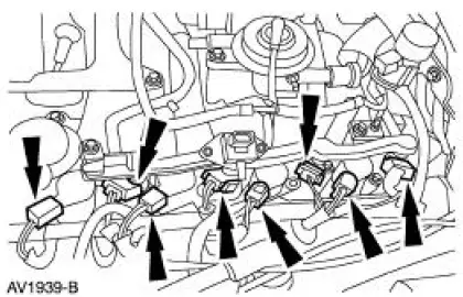
10. Connect the following connectors:
- LH fuel injectors
- LH ignition coils
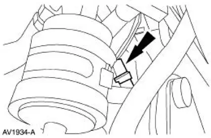
11. Connect the following generator connectors:
- Voltage regulator
- Battery supply
12. Install the wiring harness retainers to the power steering reservoir bracket.
13. Connect the following connectors:
- LH radio ignition interference capacitor
- CMP sensor
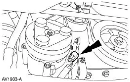
14. Connect the coolant reservoir electrical connector.
15. Raise the vehicle.
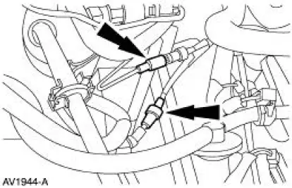
16. Connect the LH (HO2S) electrical connector.
17. Connect the RH (HO2S) electrical connector.
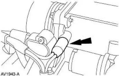
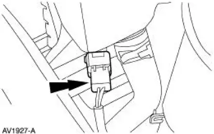
18. Connect the A/C compressor clutch electrical connector.
19. Connect the CKP electrical connector.
20. Lower the vehicle.
21. Connect the 16 pin connector.
22. Connect the following connectors:
- ECT sensor
- RH radio ignition interference capacitor
23. Connect the following connectors:
- PCV hose
- Four fuel injectors
- Four ignition coils
24. Connect the following connectors:
- IAC valve
- TP sensor

25. Install the wiring harness retainers to the dash panel.
26. Connect the 42 pin connector.
27. Connect the air cleaner outlet tube.
28. Connect the battery ground cable.
 Removal
WARNING: Do not smoke or carry lighted tobacco or open flame of any
type when
working on or near any fuel related components. Highly flammable mixtures are
always present
and may be ignited. Failure ...

Other materials:
Installation
All vehicles
1. NOTE: Inspect the insulators for wear or damage. Install new
insulators if necessary.
Install the upper insulator on the spring.
2. Install the lower insulator on the lower arm.
3. Install the rear spring. Make sure the pigtail on the low ...
Moulding - Roof Side
Removal and Installation
1. Remove the weatherstrip.
2. Remove the exterior roof side moulding screws.
3. Remove the interior roof side moulding screws.
4. Remove the roof side moulding screw.
5. Release the clips.
1. Lift up to release the two ...
Removal
1. Remove the A/C compressor (19703). For additional information, refer to
Air Conditioning (A/C)
Compressor-3.8L or Air Conditioning (A/C) Compressor-4.6L in this section.
2. Remove the bolt.
1. Hold the A/C disc and hub assembly (19D786) with the special ...
