Ford Mustang (1999-2004) Service Manual: Removal
1. Remove the differential assembly from the differential housing. For additional information, refer to Differential Case in this section.
2. CAUTION: Record the torque necessary to maintain rotation of the drive pinion gear through several revolutions prior to removing the pinion flange (4851).
Remove the pinion flange. For additional information, refer to Drive Pinion Flange and Drive Pinion Seal in this section.
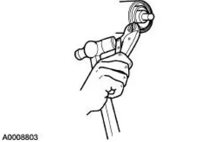
3. Force the rear axle drive pinion seal metal flange up. Install gripping pliers and strike with a hammer to remove the seal.
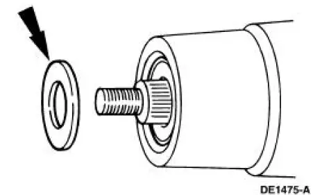
4. Remove the rear axle drive pinion shaft oil slinger (4670).
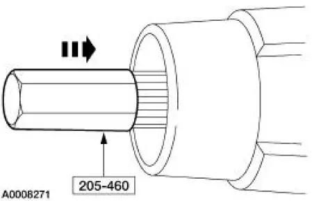
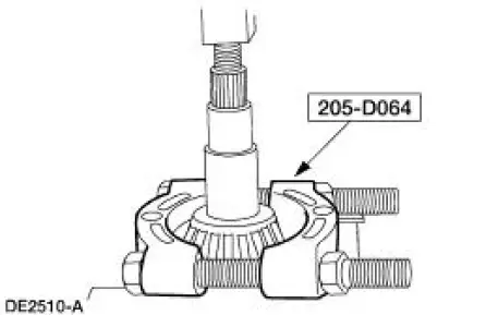
5. Using the special tool and a soft-faced hammer, drive the pinion assembly out of the outer differential pinion bearing (4621) and remove the drive pinion through the rear of the differential housing (4010).
6. Remove the outer differential pinion bearing.
7. Remove and discard the collapsible spacer (4662).
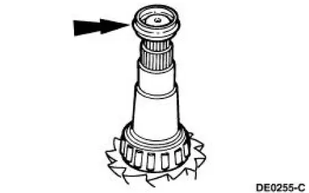
8. Using the special tool and a suitable press, remove the inner differential pinion bearing (4630).
9. NOTE: Do not remove the pinion bearing cups from the differential housing unless the cups are damaged.
Using the special tools, remove the outer differential drive pinion bearing cup (4616).
10. Using the special tools, remove the inner rear axle pinion bearing cup (4628).
 Drive Pinion
Special Tool(s)
Adapter for 205-S127
205-105 (T76P-4020-A3)
Adapter for 205-S127
205-109 (T76P-4020-A9)
Adapter for 205-S127
205-110 (T76P-4020-A10)
Adapter fo ...
 Installation
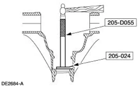
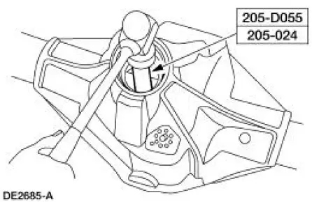
Using special tool 205-024
NOTE: This is the preferred method for installing the pinion bearing
cups. If necessary, proceed to
Using special tools 205-153, 205-024, 205-231, and 205-D055 in this proc ...
Other materials:
Diagnostic Trouble Code Charts
Diagnostic Trouble Code Chart
Five
Digit
DTC
Component
Description
Condition
Symptom
Action
P0102
P0103
P1100
P1101
MAF
MAF concerns
MAF system has a
malfunction which
may cause a
transmission
concern.
High or low ...
Lamp Assembly - Map/Dome
Removal
1. Disconnect the battery ground cable.
2. Remove the lamp lens from the lamp assembly.
3. Remove the lamp assembly.
1. Remove the screws.
2. Remove the lamp assembly.
Disconnect the electrical connectors.
Installation
1. NOTE ...
Essential towing checks
Follow these guidelines for safe towing:
• Do not tow a trailer until you drive your vehicle at least 1000 miles
(1600 kilometers).
• Consult your local motor vehicle laws for towing a trailer.
• See the instructions included with towing accessories for ...
