Ford Mustang (1999-2004) Service Manual: Removal
1. Disconnect the battery negative cable.
2. Drain the engine cooling system.
3. Remove the RH exhaust manifold. For additional information, refer to Exhaust Manifold RH in this section.
4. Remove the lower intake manifold. For additional information, refer to Lower Intake Manifold in this section.
5. Remove the push rods. For additional information, refer to Push Rod in this section.
6. Remove the drive belt.
7. Disconnect the A/C manifold and tube assembly.
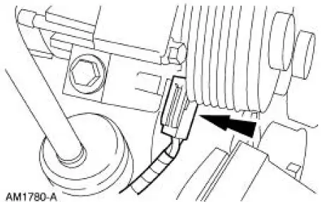
8. Disconnect the A/C compressor clutch electrical connector.
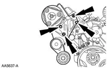
9. Remove the A/C compressor bracket.
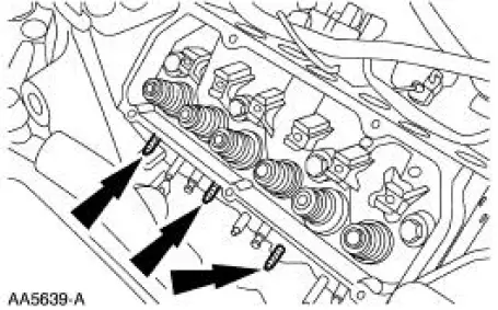
10. Remove the three exhaust manifold studs.
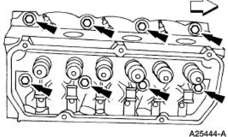
11. NOTE: Discard the cylinder head gasket.
NOTE: Record the location of the long bolts and the short bolts.
Remove the cylinder head. Discard the cylinder head bolts.
 Cylinder Head RH
Material
...
 Installation
NOTE: Do not use a fiber disc to clean the surfaces. Fibers from
the disc can get into the oil pan and
oil and clog the oil bypass valve.
1. Clean and inspect the cylinder head for flatness.
2. ...
Other materials:
Personal Safety System
The Personal Safety System provides an improved overall level of frontal
crash protection to front seat occupants and is designed to help further
reduce the risk of airbag-related injuries. The system is able to analyze
different occupant conditions and crash ...
Driveline Angle
Item
Description
1
Bottom of the frame
2
Engine crankshaft centerline
3
Engine angle
4
Driveshaft and coupling shaft centerline
5
Driveshaft and coupling shaft angle
6
Rear axle pinion centerline ...
Evaporative Emissions (Diagnosis and Testing)
Special Tool(s)
Evaporative Emission System
Leak Tester
310-F007 (134-00056) or
equivalent
Worldwide Diagnostic System
(WDS)
418-F224,
New Generation STAR (NGS)
Tester
418-F052, or equivalent scan
tool
Evaporative Em ...
