Ford Mustang (1999-2004) Service Manual: Removal
1. Disconnect the battery ground cable. For additional information, refer to Section.
2. Remove the transmission.
3. Remove the air intake scoop. For additional information, refer to Section.
4. Remove the air cleaner outlet tube. For additional information, refer to Section.
5. Remove the radiator sight shield.
6. Remove the manifold and tube assembly-accumulator to compressor, 4.6L. For additional information, refer to Section.
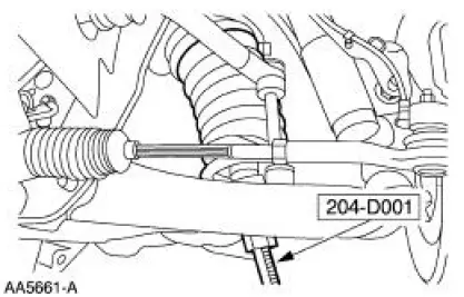
7. Remove the A/C line. For additional information, refer to Section.
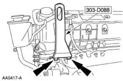
8. Install the special tools.
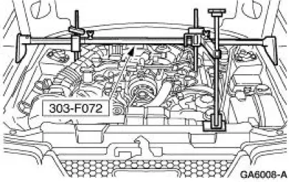
9. Install the special tool.
10. Raise the vehicle on a hoist. For additional information, refer to Section.
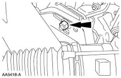
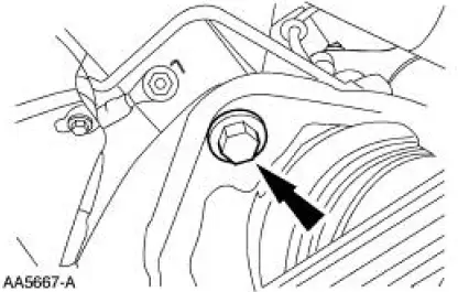
11. Remove the two engine mount nuts.
12. Lower the vehicle.
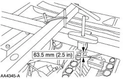
13. Using the special tool, raise the engine.
14. Raise the vehicle on a hoist.
15. Remove the oil pan drain plug and drain the engine oil.
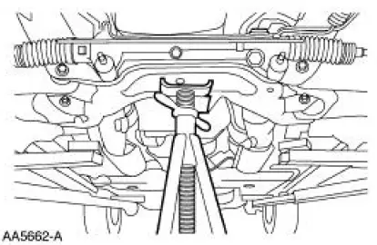
16. Using the special tool, compress the front coil springs.
17. Position a safety stand.
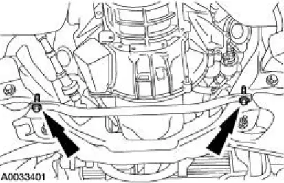
18. Remove the four bolts.
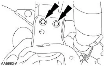
19. NOTE: Do not completely remove the bolts.
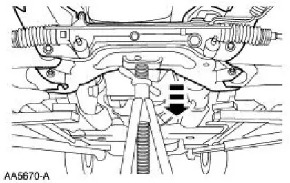
Loosen the bolts.
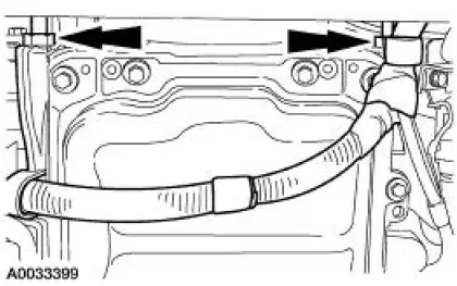
20. Lower the front sub-frame.
21. Remove the sub-frame brace.
22. Remove the starter wiring harness nuts and position the wiring harness out of the way.
23. NOTE: Be careful when removing the oil pan gasket. It is reusable.
Remove the oil pan and gasket.
- Inspect the oil pan gasket for damage.
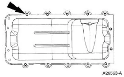
 Oil Pan
Special Tool(s)
Compressor, Coil Spring
204-D001 (D78P-5310-A)
Lifting Bracket, Engine
303-D088 (D93P-6001-A2)
3-Bar Engine Support Kit
303-F072
Materia ...
 Installation
1. CAUTION: Do not use metal scrapers, wire brushes, power abrasive
discs or other
abrasive means to clean the sealing surfaces. These tools cause scratches and
gouges
which make leak paths. Use a p ...
Other materials:
Degas Bottle
Removal and Installation
1. Drain the coolant. For additional information, refer to Supercharger
Cooling System Draining,
Filling and Bleeding in this section.
2. Disconnect the coolant hoses.
3. Remove the bolts and the degas bottle.
4. To install ...
Inspection and Verification
1. Verify the customer concern.
2. Visually inspect for obvious signs of electrical damage.
Visual Inspection Chart
Electrical
Central junction box (CJB) Fuse 31 (5A)
Damaged wiring harness
Loose or corroded connections
...
Hydraulic System
Fluid Pump
The transmission uses a gerotor-type design front pump support and gear. The
pump provides the
volume of fluid needed to charge the torque converter, main control assembly,
cooling system and
lube system. Pump pressure is regu ...
