Ford Mustang (1999-2004) Service Manual: Paint Codes
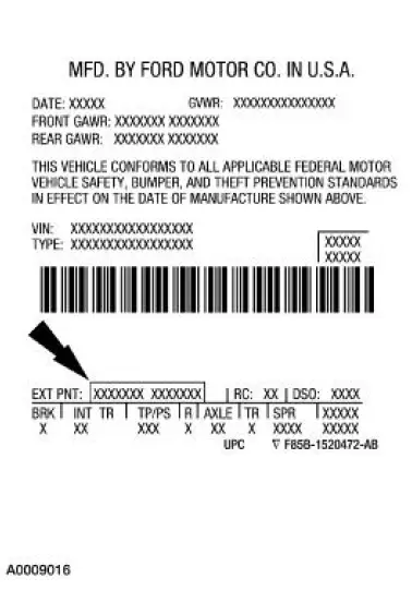
The first set of paint code letters/numbers listed indicate the vehicle primary body color. The second set of paint code letters/numbers listed (if applicable) indicate a two-tone or accent body color.
- B7 - Zinc Yellow (clear coat)
- CX - Dark Shadow Gray Metallic
- D3 - Colorado Red (clear coat)
- G2 - Redfire (water based) clear coat
- L2 - True Blue (water based) clear coat
- L5 - Azure Blue (water based) clear coat (Mach One only)
- SN - Sonic Blue (water based) clear coat
- SU - Amazon Green (water based) clear coat
- UA - Ebony (clear coat)
- YN - Silver Metallic (water based) clear coat
- Z1 - Oxford White (clear coat)
Brake Codes
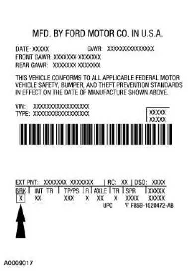
The brake type codes are:
- 2 - Four-wheel disc with anti-lock brake system (ABS)
- 3 - Traction control
- 5 - Four-wheel disc with anti-lock brake system (ABS) and traction control
 Vehicle Certification (VC) Label Locator
The upper portion of the vehicle certification (VC) label contains the
manufacturer name, the month
and year of manufacture, the certification statement and the VIN. It also
includes gross vehicle ...
 Interior Trim Codes
The interior trim codes are listed below. The first letter/number is for the
interior fabric. The second
letter is for the interior color.
9 - Quantum/Rhodes cloth (base coupe)
A - Link weave cl ...
Other materials:
Air Cleaner Outlet Pipe - 3.8L
Removal and Installation
1. Remove the air cleaner outlet tube.
1. Loosen the clamps.
2. Disconnect the hose.
3. Remove the tube.
2. To install, reverse the removal procedure.
Air Cleaner Outlet Pipe -4.6L (2V)
Removal and Installation
1. Dis ...
Air Conditioning Line (Peanut) Fitting
Disconnect
1. CAUTION: Support the female fitting with a wrench to prevent the
tubes from
twisting.
Remove the nut from the peanut fitting.
2. Pull the peanut fitting apart.
3. CAUTION: Do not use metal tools to remove the O-ring seal. They can
cause axi ...
Accessories
For a complete listing of the accessories that are available for your
vehicle, please contact an authorized dealer or visit our online store at
Accessories.Ford.com (United States only).
Ford Custom Accessories are available for your vehicle through an
author ...
