Ford Mustang (1999-2004) Service Manual: Seats (Description and Operation)
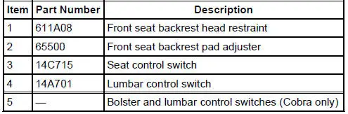
Seats - Front Power
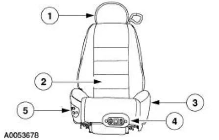
The front power seat features:
- a six-way seat regulator control switch (14A701) located on the front of the seat.
- a seat track (61705) mounted under the seat.
- a seat regulator motor (14547) and gear housing mounted on the seat track (61705).
- an optional power lumbar switch located on the outboard side of the seat (14C715).
- a manual seat backrest release handle on the outboard rear corner of the seat.
- an optional power bolster and lumbar switches located on the inboard side of the seat (Cobra only)
Seats - Power Lumbar Support
NOTE: The pump and solenoid module are serviced as an assembly with the front seat cushion frame (Cobra only). The backrest bolster/lumbar adjusting pads are serviced together and the cushion bolsters are serviced separately.
The power lumbar support system consists of:
- seat control switch (14C715)
- front seat backrest pad adjusting pump (65530)
- front seat adjusting motor drive tube (618B62)
- system wiring and circuit protection
- front seat backrest adjusting hose (65528)
- driver backrest and cushion bolster (Cobra)
- driver bolster and lumbar adjusting pad pump motor and solenoid module (Cobra)
- driver bolster and lumbar control switch (Cobra)
- driver seat cushion adjusting hose (Cobra)
Seats - Front Seat Backrest Latch
NOTE: Under no circumstances are the front seat backrest latch components to be repaired as individual components. If a front seat backrest latch (62648) or component is non-functional or damaged, a new front seat backrest latch must be installed.
A release handle on the outboard rear corner of the seat backrest is manually operated to unlock the front seat backrest latch.
Rear Seat
The rear seat cushion pad and frame (600A88) is retained in the following manner:
- Pins are located on the bottom front of the rear seat cushion pad and frame which secure the rear seat cushion pad and frame to the front floor pan (11135).
- The pins are inserted into locking plates on the floor crossmember with a push button release.
- The bottom of the rear seatback frame is retained with screws to the front floor pan.
 Seating
Torque Specifications
...
 Seats (Diagnosis and Testing)
Refer to Wiring Diagrams Cell 120 , Power Seats for schematic and
connector information.
Refer to Wiring Diagrams Cell 122 , Power Lumbar Seats for schematic and
connector information.
Special ...
Other materials:
Differential Case and Ring Gear
Special Tool(s)
2-Jaw Puller
205-D072 (D97L-4221-A) or
equivalent
Installer, Differential Side
Bearing
205-009 (T57L-4221-A1)
Step Plate
205-D016 (D80L-630-5) or
equivalent
...
Pressure Relief
Special Tool(s)
Fuel Pressure Gauge
310-012 (T80L-9974-B)
WARNING: Do not smoke or carry lighted tobacco or open flame of any
type when
working on or near any fuel-related components. Highly flammable mixtures are
always present
and may be ig ...
Transmission Cooling
Inspection and Verification
WARNING: Never remove the radiator cap under any conditions while the engine
is
operating. Failure to follow these instructions could result in personal injury
and/or damage to
the cooling system or engine. To avoid having scaldin ...
