Ford Mustang (1999-2004) Service Manual: Seats (Diagnosis and Testing)
Refer to Wiring Diagrams Cell 120 , Power Seats for schematic and connector information.
Refer to Wiring Diagrams Cell 122 , Power Lumbar Seats for schematic and connector information.
Special Tool(s)
 |
73 III Automotive Meter 105-R0057 |
Inspection and Verification
1. Verify the customer concern by operating the system.
2. Visually inspect for obvious signs of mechanical or electrical damage.
Visual Inspection Chart
| Mechanical | Electrical |
|
|
3. If an obvious cause for an observed or reported concern is found, correct the cause (if possible) before proceeding to the next step.
4. If the concern is not visually evident, verify the symptom. GO to Symptom Chart .
Symptom Chart
Refer to the Wiring Diagram manual for the connector numbers cited in the pinpoint tests.
| Condition | Possible Sources | Action |
|
|
|
|
|
|
|
|
|
|
|
|
|
|
|
|
|
|
Pinpoint Tests
PINPOINT TEST A: THE POWER SEAT IS INOPERATIVE
| Test Step | Result / Action to Take |
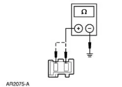
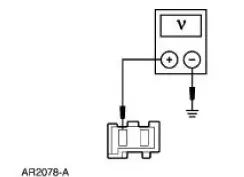
| A1 CHECK CIRCUIT 566 (DG) | Yes GO to A2 . No REPAIR the circuit. TEST the system for normal operation. |
|
|
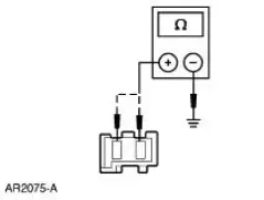
| A2 CHECK CIRCUIT 1205 (BK) FOR AN OPEN | Yes GO to A3 . No REPAIR the circuit. TEST the system for normal operation |
|
|
| A3 CHECK THE SEAT REGULATOR CONTROL SWITCH | Yes CHECK for obstructed or binding seat track. If no obstructions are found, INSTALL a new seat track. REFER to Seat Track . TEST the system for normal operation. No INSTALL a new seat regulator control switch. REFER to Switch-Seat Regulator Control . TEST the system for normal operation. |
|
PINPOINT TEST B: THE POWER SEAT DOES NOT MOVE VERTICALLY - FRONT
| Test Step | Result / Action to Take |
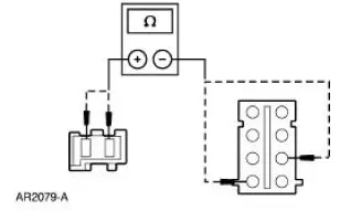
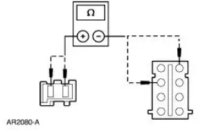
| B1 CHECK THE MOTOR SUPPLY CIRCUITS | Yes GO to B3 . No GO to B2 . |
|
|
| B2 CHECK CIRCUIT 979 (RD/LB) AND 990 (YE/LB) FOR AN OPEN | Yes INSTALL a new seat regulator control switch. REFER to Switch- Seat Regulator Control . TEST the system for normal operation. No REPAIR the circuit. TEST the system for normal operation. |
|
|
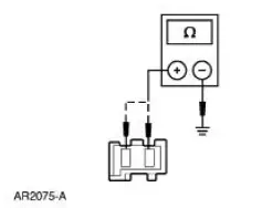
| B3 CHECK CIRCUIT 979 (RD/LB) AND 990 (YE/LB) FOR A SHORT TO GROUND | Yes GO to B4 . No REPAIR the circuit. TEST the system for normal operation. |
|
|
| B4 CHECK THE UP POSITION INPUT | Yes GO to B5 . No INSTALL a new seat regulator control switch. REFER to Switch- Seat Regulator Control . TEST the system for normal operation. |
|
|
| B5 CHECK THE DOWN POSITION INPUT | Yes INSTALL a new seat track. REFER to Seat Track . TEST the system for normal operation. No INSTALL a new seat regulator control switch. REFER to Switch- Seat Regulator Control . TEST the system for normal operation. |
|
PINPOINT TEST C: THE POWER SEAT DOES NOT MOVE VERTICALLY - REAR
| Test Step | Result / Action to Take |
| C1 CHECK THE MOTOR SUPPLY CIRCUITS | Yes GO to C3 . No GO to C2 . |
|
|
| C2 CHECK CIRCUIT 983 (RD/LG) AND 982 (YE/LG) FOR AN OPEN | Yes INSTALL a new seat regulator control switch. REFER to Switch- Seat Regulator Control . TEST the system for normal operation. No REPAIR the circuit. TEST the system for normal operation. |
|
|
| C3 CHECK CIRCUIT 983 (RD/LG) AND 982 (YE/LG) FOR A SHORT TO GROUND | Yes GO to C4 . No REPAIR the circuit. TEST the system for normal operation. |
|
|
| C4 CHECK THE UP POSITION INPUT | Yes GO to C5 . No INSTALL a new seat regulator control switch. REFER to Switch- Seat Regulator Control . TEST the system for normal operation. |
|
|
| C5 CHECK THE DOWN POSITION INPUT | Yes INSTALL a new seat track. REFER to Seat Track . TEST the system for normal operation. No INSTALL a new seat regulator control switch. REFER to Switch- Seat Regulator Control . TEST the system for normal operation. |
|
PINPOINT TEST D: THE POWER SEAT DOES NOT MOVE HORIZONTALLY
| Test Step | Result / Action to Take |
| D1 CHECK THE MOTOR SUPPLY CIRCUITS | Yes GO to D3 . No GO to D2 |
|
|
| D2 CHECK CIRCUIT 981 (RD/WH) AND 980 (YE/WH) FOR AN OPEN | Yes INSTALL a new seat regulator control switch. REFER to Switch- Seat Regulator Control . TEST the system for normal operation. No REPAIR the circuit. TEST the system for normal operation. |
|
|
| D3 CHECK CIRCUIT 981 (RD/WH) AND 980 (YE/WH) FOR A SHORT TO GROUND | Yes GO to D4 . No REPAIR the circuit. TEST the system for normal operation. |
|
|
| D4 CHECK THE REARWARD POSITION INPUT | Yes GO to D5 . No INSTALL a new seat regulator control switch. REFER to Switch- Seat Regulator Control . TEST the system for normal operation. |
|
|
| D5 CHECK THE FORWARD POSITION INPUT | Yes INSTALL a new seat track. REFER to Seat Track . TEST the system for normal operation. No INSTALL a new seat regulator control switch. REFER to Switch- Seat Regulator Control . TEST the system for normal operation. |
|
PINPOINT TEST E: THE POWER LUMBAR IS INOPERATIVE
| Test Step | Result / Action to Take |
| E1 CHECK THE LUMBAR COMPRESSOR OPERATION | Yes GO to E6 . No GO to E2 . |
|
|
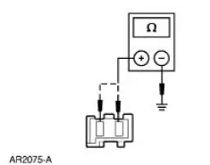
| E2 CHECK CIRCUIT 566 (DG) | Yes GO to E3 . No REPAIR the circuit. TEST the system for normal operation. |
|
|
|
E3 CHECK CIRCUIT 1205 (BK) FOR AN OPEN |
Yes GO to E4 . No REPAIR the circuit. TEST the system for normal operation. |
|
|
| E4 CHECK THE POWER SUPPLY TO THE LUMBAR MOTOR | Yes INSTALL a new lumbar motor. REFER to Lumbar Motor . TEST the system for normal operation. No GO to E5 . |
|
|
| E5 CHECK CIRCUIT 51 (BK/WH) FOR AN OPEN | Yes INSTALL a new lumbar seat control switch. REFER to Lumbar Control Switch . TEST the system for normal operation. No REPAIR the circuit. TEST the system for normal operation. |
|
|
| E6 CHECK THE LUMBAR ADJUSTING SYSTEM | Yes GO to E10 . No GO to E7 . |
|
|
| E7 CHECK THE SEAT BACKREST LUMBAR ADJUSTING PAD | Yes INSTALL a new seat backrest lumbar adjusting pad. REFER to Lumbar Assembly . TEST the system for normal operation. No GO to E8 . |
|
|
| E8 CHECK AIR FLOW FROM LUMBAR COMPRESSOR | Yes GO to E9 . No INSTALL a new lumbar motor. REFER to Lumbar Motor . TEST the system for normal operation |
|
|
| E9 CHECK THE AIR FLOW FROM THE LUMBAR SEAT CONTROL SWITCH | Yes GO to E10 . No INSTALL a new seat backrest lumbar adjusting hose. TEST the system for normal operation. |
|
|
| E10 CHECK THE SYSTEM FOR LEAKS | Yes The system is operating correctly. TEST the system for normal operation. No GO to E11 . |
|
|
| E11 CHECK THE SEAT BACKREST LUMBAR ADJUSTING PAD FOR LEAKS | Yes INSTALL a new lumbar seat control switch. REFER to Lumbar Control Switch . TEST the system for normal operation. No INSTALL a new seat backrest lumbar adjusting pad. REFER to Lumbar Assembly . TEST the system for normal operation. |
|
PINPOINT TEST F: THE POWER BOLSTER/LUMBAR IS INOPERATIVE - DRIVER
| Test Step | Result / Action to Take |
| F1 CHECK THE BOLSTER/LUMBAR COMPRESSOR OPERATION | Yes GO to F5 . No GO to F2 . |
|
|
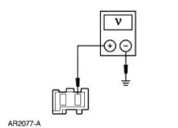
| F2 CHECK CIRCUIT (BK) FOR VOLTAGE | Yes GO to F3 . No REPAIR the circuit. TEST the system for normal operation. |
|
|
| F3 CHECK CIRCUIT (LG) FOR AN OPEN | Yes GO to F4 . No REPAIR the circuit. TEST the system for normal operation. |
|
|
| F4 CHECK THE BOLSTER/LUMBAR SEAT CONTROL SWITCHES | Yes INSTALL a new bolster/lumbar pump and solenoid module. REFER to Lumbar Motor . TEST the system for normal operation. No INSTALL a new bolster/lumbar seat control switch. REFER to Lumbar Control Switch . TEST the system for normal operation. |
|
|
| F5 CHECK THE LUMBAR ADJUSTING SYSTEM | Yes GO to F9 . No For seat backrest lumbar, GO to F6 . For seat backrest bolster, GO to F10 . For seat cushion bolster, GO to F14 |
|
|
| F6 CHECK THE SEAT BACKREST LUMBAR ADJUSTING PAD | Yes INSTALL a new seat backrest lumbar adjusting pad. REFER to Lumbar Assembly . TEST the system for normal operation. No GO to F7 |
|
|
| F7 CHECK AIR FLOW FROM LUMBAR COMPRESSOR | Yes GO to F8 . No INSTALL a new bolster/lumbar pump and solenoid module. REFER to Front Seat Cushion . TEST the system for normal operation |
|
|
| F8 CHECK THE SYSTEM FOR LEAKS | Yes The system is operating correctly. TEST the system for normal operation. No GO to F9 . |
|
|
| F9 CHECK THE SEAT BACKREST LUMBAR ADJUSTING PAD FOR LEAKS | Yes INSTALL a new bolster/lumbar pump and solenoid module. REFER to Lumbar Motor . TEST the system for normal operation. No INSTALL a new seat backrest lumbar adjusting pad. REFER to Lumbar Assembly . TEST the system for normal operation. |
|
|
| F10 CHECK THE SEAT BACKREST BOLSTER ADJUSTING PADS | Yes INSTALL a new seat backrest bolster adjusting pad. REFER to Lumbar Assembly . TEST the system for normal operation. No GO to F11 . |
|
|
| F11 CHECK AIR FLOW FROM BOLSTER COMPRESSOR | Yes GO to F12 . No INSTALL a new bolster/lumbar pump and solenoid module. REFER to Lumbar Motor . TEST the system for normal operation. |
|
|
| F12 CHECK THE SYSTEM FOR LEAKS | Yes The system is operating correctly. TEST the system for normal operation. No GO to F13 . |
|
|
| F13 CHECK THE SEAT BACKREST BOLSTER ADJUSTING PAD FOR LEAKS | Yes INSTALL a new bolster/lumbar pump and solenoid module. REFER to Lumbar Motor . TEST the system for normal operation. No INSTALL a new seat backrest bolster adjusting pad. REFER to Lumbar Assembly . TEST the system for normal operation. |
|
|
| F14 CHECK THE SEAT CUSHION BOLSTER ADJUSTING PADS | Yes INSTALL a new seat cushion bolster adjusting pad. REFER to Lumbar Assembly . TEST the system for normal operation. No GO to F15 |
|
|
| F15 CHECK AIR FLOW FROM BOLSTER COMPRESSOR | Yes GO to F16 . No INSTALL a new bolster/lumbar pump and solenoid module. REFER to Lumbar Motor . TEST the system for normal operation. |
|
|
| F16 CHECK THE SYSTEM FOR LEAKS | Yes The system is operating correctly. TEST the system for normal operation. No GO to F17 . |
|
|
| F17 CHECK THE SEAT CUSHION BOLSTER ADJUSTING PAD FOR LEAKS | Yes INSTALL a new bolster/lumbar pump and solenoid module. REFER to Lumbar Motor . TEST the system for normal operation. No INSTALL a new seat cushion bolster adjusting pad. REFER to Lumbar Assembly . TEST the system for normal operation. |
|
 Seats (Description and Operation)
Seats - Front Power
The front power seat features:
a six-way seat regulator control switch (14A701) located on the
front of the seat.
a seat track (61705) mounted under the seat.
...
 Switch - Seat Regulator Control
Removal and Installation
1. Disconnect the battery. For additional information, refer to Section.
2. Remove the screws and position the seat regulator control switch aside.
3. Disconnect the elec ...
Other materials:
Cable and Bracket
Removal
1. Raise the vehicle on a hoist. For additional information, refer to
Section.
2. Remove the cable shift from the shifter lever and bracket and discard
the clip.
3. Remove the bolt from the cable.
4. Remove the bolt from the cable.
5. ...
Heated seats
WARNING: Persons who are unable to feel pain to the skin
because of advanced age, chronic illness, diabetes, spinal cord
injury, medication, alcohol use, exhaustion, or other physical conditions,
must exercise care when using the seat heater. The seat heater m ...
Drive Pinion
Special Tool(s)
Adapter for 205-S127
205-105 (T76P-4020-A3)
Adapter for 205-S127
205-109 (T76P-4020-A9)
Adapter for 205-S127
205-110 (T76P-4020-A10)
Adapter for 205-S127
205-111 (T76P-4020-A11)
Adapter for 20 ...
