Ford Mustang (1999-2004) Service Manual: Switch - Horn
Removal
1. Remove the driver side air bag module (043B13). Refer to Section.
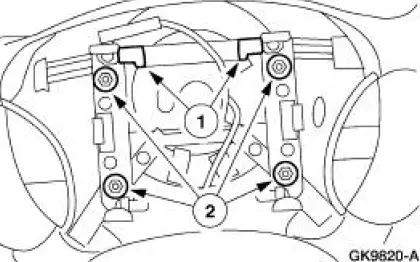
2. Remove the switches.
1. Disconnect the horn wire from the switches.
2. Remove the horn switch screws and remove the switches.
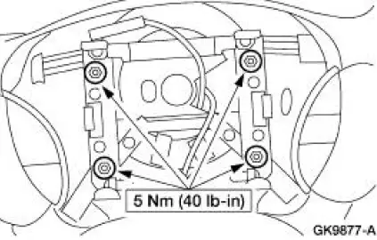
Installation
1. To install, reverse the removal procedure.
- Prove out the air bag system. Refer to Section.
 Horn (Diagnosis and Testing)
Refer to Wiring Diagrams Cell 44 , Horns/Cigar Lighter for schematic
and connector information.
Special Tool(s)
73 Digital Multimeter or
equivalent
105-R0051
Inspection and Veri ...
 Warning Devices
Warning Devices
The warning device system consists of the following components:
door ajar switches
generic electronic module (GEM)
key-in-ignition warning switch
safety belt switch
...
Other materials:
Installation
1. Lubricate the lip of the wheel bearing oil seal
Use Premium Long-Life Grease XG-1-C or equivalent meeting Ford
specification ESAM1C75-
B.
2. CAUTION: Do not damage the wheel bearing oil seal.
Install the two axle shafts.
3. CAUTION: Do not damage th ...
Heater Core Backflushing
Special Tool(s)
Flush Kit
164-R3658 or equivalent
Drain Kit
164-R3662 or equivalent
Material
Item
Specification
Motorcraft Premium Cooling
System Flush
VC-1 or equivalent
ESR-M14P7-A
Motorcraft Premium ...
Technical specifications
Wheel Lug Nut Torque Specifications
WARNING: When a wheel is installed, always remove any
corrosion, dirt or foreign materials present on the mounting
surfaces of the wheel or the surface of the wheel hub, brake drum or
brake disc that contacts the wheel. Make ...
