Ford Mustang (1999-2004) Service Manual: Transmission (DISASSEMBLY)
Special Tool(s)
|
|
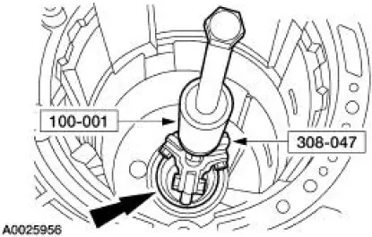
Slide Hammer 100-001 (T50T-100-A) |
|
|
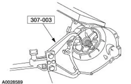
Holding Fixture, Transmission 307-003 (T57L-500-B) |
|
|
Slide Hammer 307-005 (T59L-100-B) |
|
|
Remover, Transmission Fluid Seal 307-048 (T74P-77248-A) |
|
|
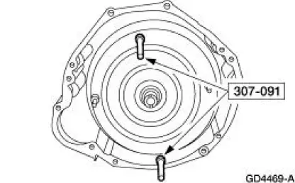
Handle, Torque Converter 307-091 (T81P-7902-C) |
|
|
Remover, Transmission Fluid Pump 307-221 (T89T-70010-A) |
|
|
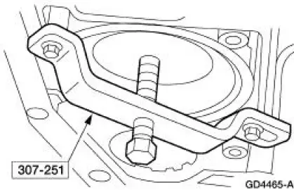
Remover/Installer, Servo Piston 307-251 (T92P-70023-A) |
|
|
Remover, Torque Converter Fluid Seal 307-309 (T94P-77001-BH) |
|
|
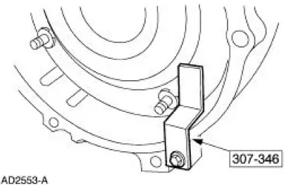
Retainer, Torque Converter 307-346 (T97T-7902-A) |
|
|
Remover, Bearing Cup 308-047 (T77F-1102-A) |
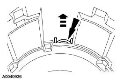
1. Remove the special tool.
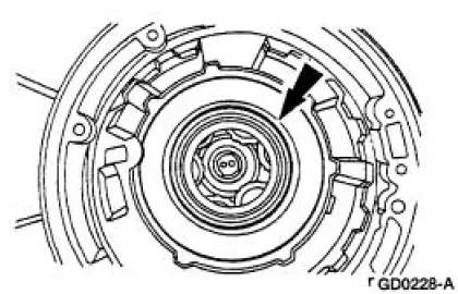
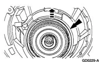
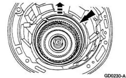
2. Using the special tools, remove torque converter.
3. Using the special tool, mount the transmission to the bench.
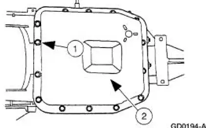
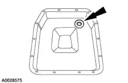
4. NOTE: If the transmission fluid pan gasket is not damaged, it may be reused.
Remove the transmission fluid pan and transmission fluid pan gasket.
1. Remove the bolts.
2. Remove the transmission fluid pan and transmission fluid pan to case gasket.
5. Clean the transmission fluid pan and pan magnet.
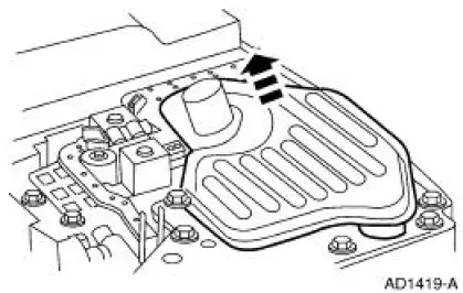
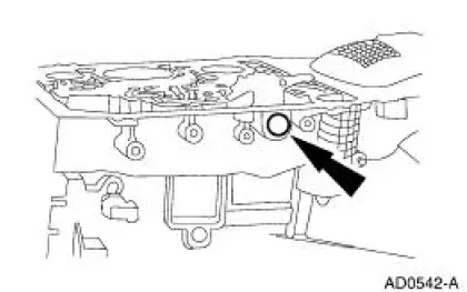
6. CAUTION: If installing a new filter, and grommet remains in the main control bore, carefully use a small screwdriver to remove the grommet. Use care not to damage the main control bore.
NOTE: If transmission is being repaired for a contamination-related failure, use a new filter and seal. The filter may be reused if no excessive contamination is present.
Remove the fluid filter and grommet.
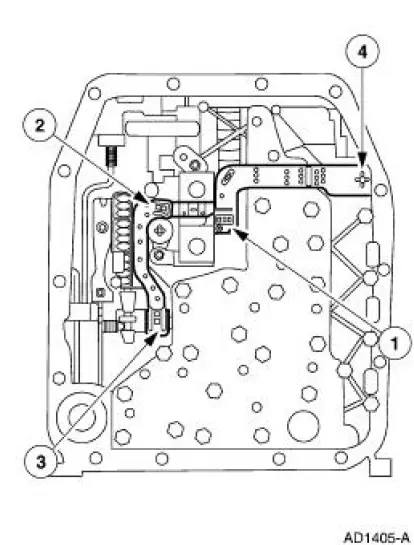
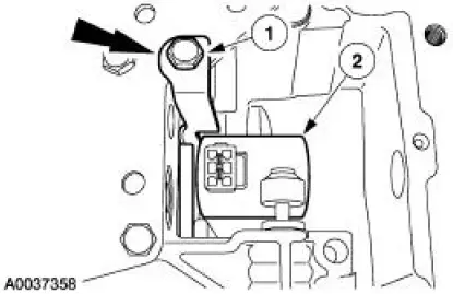
7. CAUTION: Do not pull on the molded lead frame. This may cause damage to the connector ends. Carefully pry up on the locking tabs to disconnect the solenoids.
Disconnect the molded lead frame from the solenoids.
Disconnect the molded lead frame from the solenoids.
1. Disconnect the shift solenoid SSA and SSB.
2. Disconnect the torque converter clutch (TCC).
3. Disconnect the electronic pressure control (EPC) solenoid.
4. Disconnect the bulkhead inter-connector.
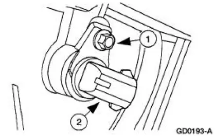
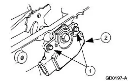
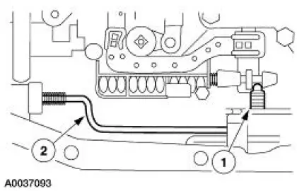
8. Remove the output shaft speed (OSS) sensor.
1. Remove the bolt.
2. Remove the OSS sensor.
9. Remove the digital transmission range (TR) sensor.
1. Remove the bolts.
2. Remove the digital TR sensor.
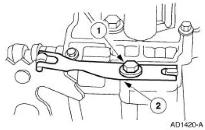
10. Remove the manual control valve detent lever spring.
1. Remove the bolt.
2. Remove the manual control valve detent lever spring.
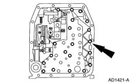
11. Remove the 24 main control valve body bolts and the main control valve body.
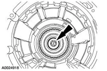
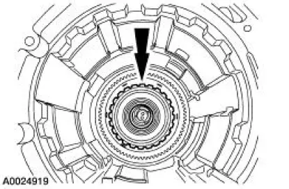
12. Remove and discard the pump outlet screen.
13. NOTE: Use a shop cloth to protect the transmission case surface.
Remove the manual lever shaft retaining pin.
14. Remove the manual lever shaft inner nut.
- Slide the manual control lever shaft out of the case while removing the inner nut.
15. Remove the parking lever actuating rod.
1. Remove the manual valve detent.
2. Remove the parking lever actuating rod.
16. CAUTION: Use care not to damage the manual control lever shaft bore. If the bore is damaged the new seal may leak.
Remove the manual control lever shaft seal.
17. Remove the EPC solenoid.
1. Remove the bolt and EPC solenoid bracket.
2. Remove the EPC solenoid.
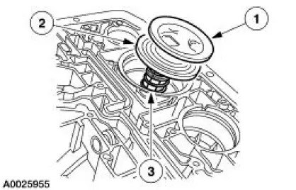
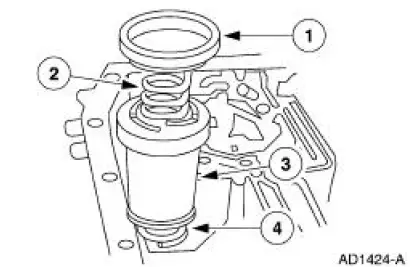
18. Remove the 2-3 accumulator spring retainer.
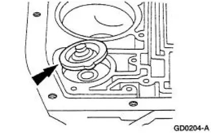
19. Remove the 2-3 accumulator piston.
1. Remove the 2-3 accumulator spring.
2. Remove the 2-3 accumulator piston.
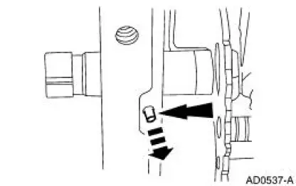
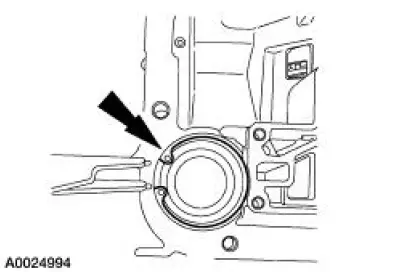
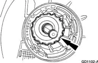
20. Using the special tool, remove the reverse band servo retaining ring.
21. Remove the reverse servo assembly.
1. Remove the reverse band servo cover.
2. Remove the reverse band servo piston and rod.
3. Remove the reverse band servo spring.
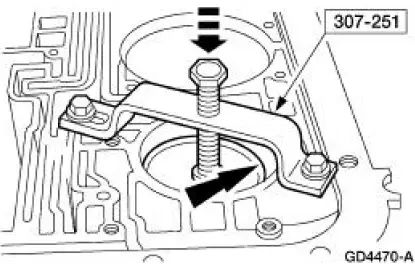
22. NOTE: If tool is not available, extreme care must be taken. Spring pressure will force overdrive servo piston assembly out of case. Case bore damage may result from trying to pry on internal retaining ring.
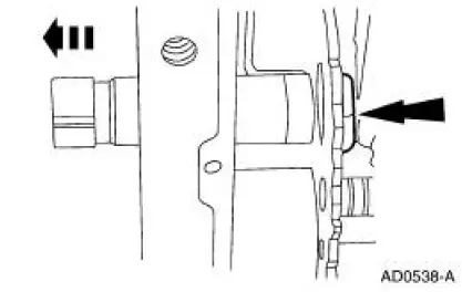
Using the special tool, compress the piston spring, then remove the overdrive servo piston retainer.
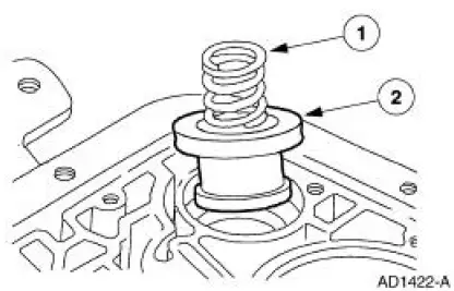
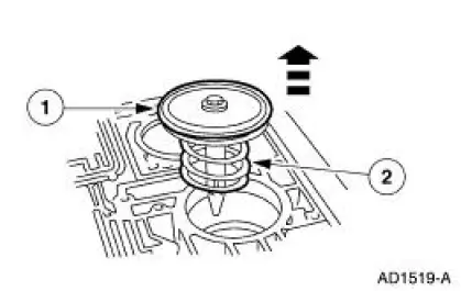
23. Remove the overdrive servo piston.
1. Remove the overdrive servo piston.
2. Remove the overdrive servo piston return spring.
24. Compress the 1-2 accumulator cover and remove the retaining ring.
25. Remove the 1-2 accumulator upper spring.
1. Remove the 1-2 accumulator spring cover.
2. Remove the 1-2 accumulator lower spring.
3. Remove the 1-2 accumulator.
4. Remove the 1-2 accumulator upper spring.
26. Using the special tools, remove the extension housing seal.
27. NOTE: These bolts have been coated with a sealant. High break torque may be required to remove these bolts.
Remove the extension housing.
1. Remove the four bolts and two nuts.
2. Remove the extension housing and the extension housing gasket.
28. Remove the parking pawl.
1. Remove the parking pawl shaft.
2. Remove the parking pawl return spring.
3. Remove the parking pawl.
29. Rotate the transmission to the vertical position with the output shaft towards the floor.
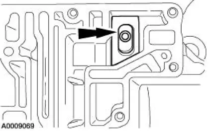
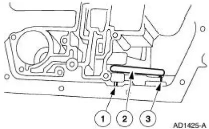
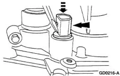
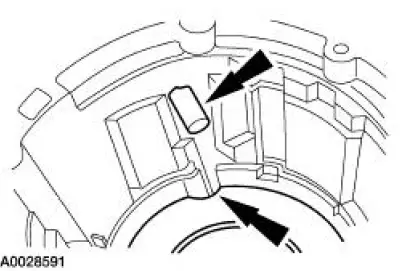
30. CAUTION: Extreme care must be taken during transmission connector removal. Do not use a hammer on the connector body.
Place a screwdriver on the flat portion of the connector and push the connector out through the bottom of the case.
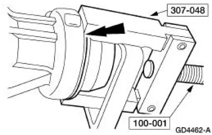
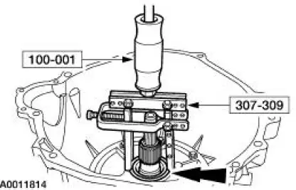
31. Using the special tools, remove the front pump seal.
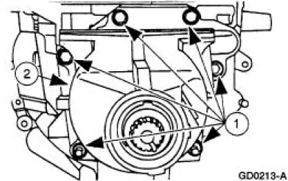
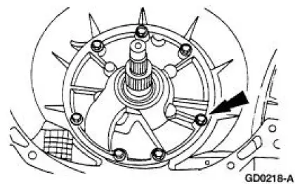
32. NOTE: These bolts have been coated with sealant. High break torque may be required to remove the bolts.
Remove the bolts.
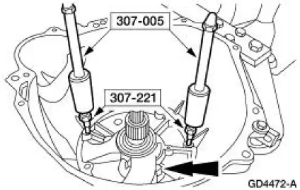
33. Using the special tools, remove the front pump support.
34. Remove and discard the pump gasket.
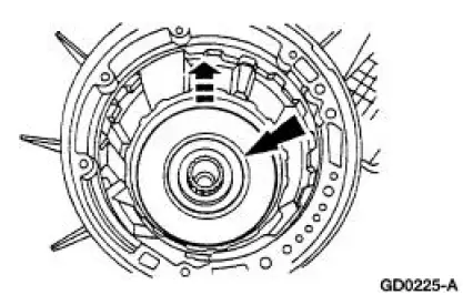
35. Remove the intermediate anti-rattle clip, if equipped.
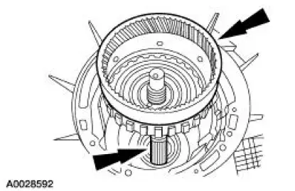
36. CAUTION: Remove the assembly carefully to prevent damage to the overdrive band friction material by the reverse clutch drive lugs.
Remove the following components as an assembly:
- Intermediate clutch pack.
- Intermediate one-way clutch.
- Reverse clutch.
- Forward clutch assembly.
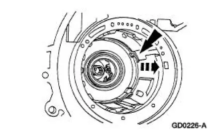
37. Disengage and remove the overdrive band.
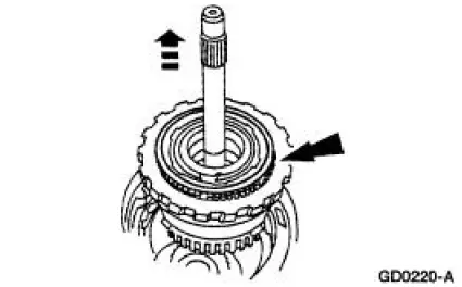
38. Remove the forward clutch hub and the No. 3 forward clutch hub front bearing.
39. Remove the intermediate stub shaft.
40. Align the reverse sun shell with the overdrive band anchor pin for removal.
41. Remove the following components as an assembly:
- Forward clutch sun gear.
- No. 5 forward clutch sun gear bearing.
- Reverse clutch sun gear.
- No. 4 forward clutch hub bearing.
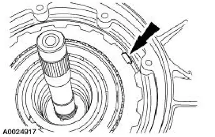
42. Remove the center support retaining ring and note location for assembly.
43. Remove the case to planet support spring.
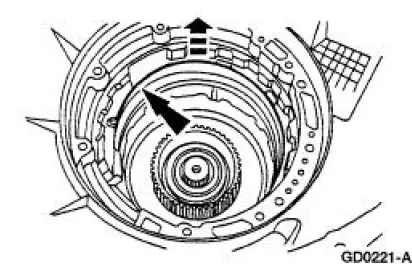
44. Remove the planetary gear support and planetary as an assembly.
45. Remove the reverse clutch band.
46. Remove the retaining ring.
47. Remove the direct clutch pack.
48. Remove the No. 8 bearing.
49. Remove the output shaft, output shaft ring gear assembly and direct clutch.
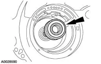
50. Remove the No. 9 case rear bearing.
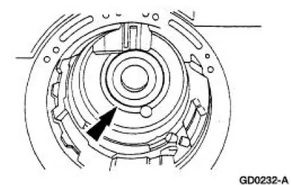
51. Inspect and if necessary, use the special tools to remove the rear case bushing.
 Transmission (REMOVAL)
Special Tool(s)
Retainer, Torque Converter
307-346 (T97T-7902-A)
CAUTION: Whenever a transmission has been disassembled to install new
parts the
transmission fluid cooler tubes must b ...

Other materials:
Air Intake Scoop Bracket
Removal and Installation
1. Remove the air intake scoop. For additional information, refer to Air
Intake Scoop in this section.
2. Remove the air intake scoop bracket nut at the throttle body.
3. Remove the exhaust gas recirculation (EGR) vacuum regulat ...
Camshaft Runout
Special Tool(s)
Dial Indicator Gauge with
Holding Fixture
100-002 (TOOL-4201-C) or
equivalent
1. NOTE: Camshaft journals must be within specifications before
checking runout.
Use a Dial Indicator Gauge with Holding Fixture to measure the ...
Symptom Chart
Condition
Possible Sources
Action
Tires show
excess wear on
edge of tread
Underinflated tires.
Vehicle overloaded.
High-speed cornering.
Incorrect ride height.
Incorrect wheel alignment.
Incorrect tire ...
