
Ford Mustang (1999-2004) Service Manual: Camshaft Runout
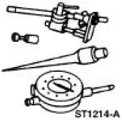
Special Tool(s)
|
|
Dial Indicator Gauge with Holding Fixture 100-002 (TOOL-4201-C) or equivalent |
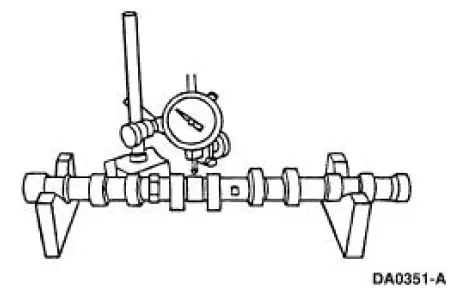
1. NOTE: Camshaft journals must be within specifications before checking runout.
Use a Dial Indicator Gauge with Holding Fixture to measure the camshaft runout.
- Rotate the camshaft and subtract the lowest indicator reading from the highest indicator reading.
- For additional information, refer to the specification chart in the appropriate engine section.
- If out of specification, install new components as necessary. Refer to the appropriate section in Group 303 for the procedure.
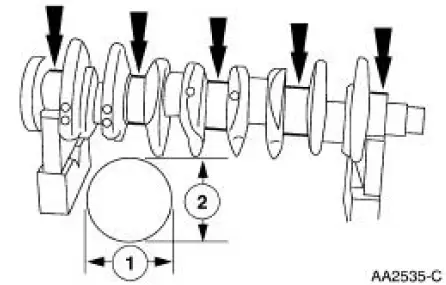
Crankshaft Main Bearing Journal -Diameter
1. Measure each of the crankshaft main bearing journal diameters in at least two directions.
- Refer to the appropriate section in Group 303 for the procedure.
- If out of specification, install new components as necessary. Refer to the appropriate section in Group 303 for the procedure.
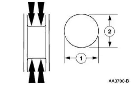
Crankshaft Main Bearing Journal -Taper
1. Measure each of the crankshaft main bearing journal diameters in at least two directions at each end of the main bearing journal.
- Refer to the appropriate section in Group 303 for the procedure.
- If out of specification, install new components as necessary. Refer to the appropriate section in Group 303 for the procedure.
 Camshaft Lobe Lift
Special Tool(s)
Dial Indicator Gauge with
Holding Fixture
100-002 (TOOL-4201-C) or
equivalent
1. Use a Dial Indicator Gauge with Holding Fixture to measure camshaft
intake/exhaust ...
 Crankshaft Main Bearing Journal - Clearance
Special Tool(s)
Plastigage
303-D031 (D81L-6002-B) or
equivalent
NOTE: Crankshaft main bearing journals must be within specifications
before checking journal
clearance.
1. Remove th ...
Other materials:
Ignition Switch
Removal
1. Disconnect the battery ground cable.
2. Remove the lower instrument panel steering column cover.
1. Remove the screws.
2. Remove the lower instrument panel steering column cover.
3. Remove the instrument panel reinforcement.
1. Rem ...
Door
Removal
1. Remove the door trim panel. For additional information, refer to
Section.
2. Disconnect the necessary electrical connectors to remove the harness
and grommet from the
door.
3. NOTE: This procedure requires an assistant.
NOTE: Mark ...
EGR System Components
The EGR system returns a portion of the exhaust gas to the intake manifold to
reduce the combustion
temperature. This results in lower nitrous oxide formation.
The powertrain control module (PCM) controls the EGR vacuum regulator solenoid .
The EG ...
