Ford Mustang (1999-2004) Service Manual: Column
Removal and Installation
All vehicles
1. Disconnect the battery ground cable and wait at least one minute to allow the depletion of the restraint system backup power supply.
2. WARNING: To avoid the risk of serious personal injury, follow all warnings, cautions, notes and instructions at the beginning of the deactivation procedure.
Deactivate the supplemental restraint system (SRS). For additional information, refer to Supplemental Restraint System (SRS) Deactivation and Reactivation in this section.
3. WARNING: To reduce the risk of serious personal injury, follow all warnings, cautions, notes and instructions in the clockspring removal and installation procedure.
Remove the clockspring (14A664).
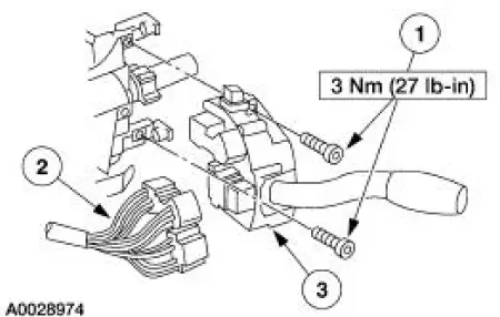
4. Remove the multi-function switch (13K359).
1. Remove the screws.
2. Disconnect the electrical connector.
3. Remove the multi-function switch.
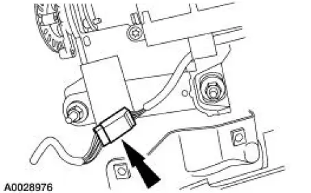
5. Disconnect the ignition switch electrical connector.
1. Remove the bolt.
2. Disconnect the electrical connector.
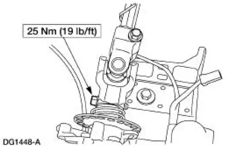
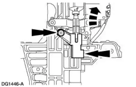
6. Remove the pinch bolt and disconnect the coupling from the steering column.
7. Disconnect the electrical connector.
Vehicles with manual transmission
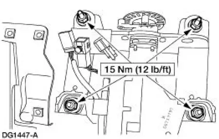
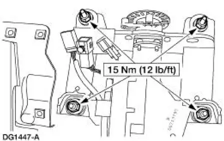
8. Remove the nuts and the steering column.
- Discard the nuts.
Vehicles with automatic transmission
9. Remove the nuts and lower the steering column.
- Discard the nuts.
10. Disconnect the ignition/shifter interlock and remove the steering column.
All vehicles
11. To install, reverse the removal procedure.
12. WARNING: To avoid the risk of serious personal injury, follow all warnings, cautions, notes and instructions at the beginning of the reactivation procedure.
Reactivate the supplemental restraint system (SRS). For additional information, refer to Supplemental Restraint System (SRS) Deactivation and Reactivation in this section.
 Wheel
Wheel
Removal and Installation
1. Disconnect the battery ground cable (14301) and wait at least one minute
to allow the depletion
of the restraint system backup power supply.
2. Turn the steering wheel ...
 Steering Column Shaft
Removal and Installation
1. CAUTION: Do not allow the steering column shaft to rotate while
intermediate shaft
is disconnected or damage to the clockspring can result. If there is evidence
that the
...
Other materials:
Air Bag Supplemental Restraint System (SRS) (Diagnosis and Testing)
Refer to Wiring Diagrams Cell 46 , Air Bag for schematic and connector
information.
Special Tool(s)
Diagnostic Tool, Restraint
System
418-F088 (105-R0012)
Restraint System Diagnostic Tool Warning
WARNING: This tool is for restraint system se ...
Front Subframe - 4.6L (4V) Engine
Special Tool(s)
3-Bar Engine Support Kit
303-F072
Lifting Bracket, Engine
303-D088 (D93P-6001-A2)
Removal and Installation
All vehicles
1. Remove the steering gear. For additional information, refer to Section .
2. Remove the low ...
Front End Body Panels
Torque Specifications
Front End Body Panels
The front end body panel components consist of the following:
air deflectors
cowl grille
fenders
fender splash shields
hood
hood hinges
hood weatherstrip
radiator grille opening panel
...
