Ford Mustang (1999-2004) Service Manual: Deactivation
WARNING: Always wear safety glasses when repairing an air bag supplemental restraint system (SRS) vehicle and when handling an air bag module. This will reduce the risk of injury in the event of an accidental deployment.
WARNING: Carry a live air bag module with the air bag and trim cover pointed away from your body. This will reduce the risk of injury in the event of an accidental deployment.
WARNING: Do not set a live air bag module down with the trim cover face down. This will reduce the risk of injury in the event of an accidental deployment.
WARNING: After deployment, the air bag surface can contain deposits of sodium hydroxide, a product of the gas generant combustion that is irritating to the skin. Wash your hands with soap and water afterwards.
WARNING: Never probe the connectors on the air bag module. Doing so can result in air bag deployment, which can result in personal injury.
WARNING: The safety belt buckle pretensioner and safety belt retractor pretensioner are pyrotechnic devices. Never probe a pretensioner electrical connector. Doing so could result in pretensioner or air bag deployment and could result in personal injury.
WARNING: Vehicle sensor orientation is critical for proper system operation. If a vehicle equipped with an air bag supplemental restraint system (SRS) is involved in a collision, inspect the sensor mounting bracket and wiring pigtail for deformation. Replace and properly position the sensor or any other damaged supplemental restraint system (SRS) components whether or not the air bag is deployed.
WARNING: The restraint system diagnostic tool is for restraint system service only.
Remove from vehicle prior to road use. Failure to remove could result in injury and possible violation of vehicle safety standards.
NOTE: If a seat equipped with a seat mounted side air bag and/or a safety belt pretensioner (if equipped) system is being serviced, the air bag system must be deactivated.
NOTE: Restraint system diagnostic tools MUST be installed under the seats in the seat side air bag (if equipped) and safety belt pretensioner (if equipped) to floor connectors.
NOTE: Diagnostics or repairs are not to be performed on a seat equipped with a seat side air bag with the seat in the vehicle. Prior to attempting to diagnose or repair a seat concern when equipped with a seat side air bag, the seat must be removed from the vehicle and the restraint system diagnostic tools must be installed in the seat side air bag electrical connectors. The restraint system diagnostic tools must be removed prior to operating the vehicle over the road.
NOTE: After diagnosing or repairing an SRS, the restraint system diagnostic tools must be removed before operating the vehicle over the road.
NOTE: After diagnosing or repairing a seat system, the restraint system diagnostic tools must be removed before operating the vehicle over the road.
NOTE: The SRS must be fully operational and free of faults before releasing the vehicle to the customer.
1. WARNING: To avoid accidental deployment and possible personal injury, the backup power supply must be depleted before repairing or replacing any front or side air bag supplemental restraint system (SRS) components and before servicing, replacing, adjusting or striking components near the front or side air bag sensors, such as doors, instrument panel, console, door latches, strikers, seats and hood latches.
Please refer to the appropriate vehicle shop manual to determine location of the front air bag sensors.
The side air bag sensors are located at or near the base of the B-pillar.
To deplete the backup power supply energy, disconnect the battery ground cable and wait at least one minute. Be sure to disconnect auxiliary batteries and power supplies (if equipped). Disconnect the battery ground cable and wait at least one minute. For additional information, refer to Section.
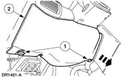
2. Remove the steering column opening lower finish panel.
1. Remove the screws.
2. Pull out to release the retaining clips and remove the steering column opening lower finish panel.
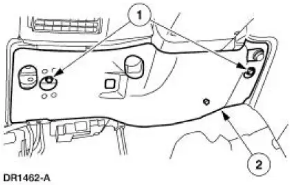
3. Remove the steering column opening lower reinforcement.
1. Remove the bolts.
2. Remove the steering column opening lower reinforcement.
4. Pushing in on the release tab, disconnect the clockspring electrical connector at the base of the steering column.
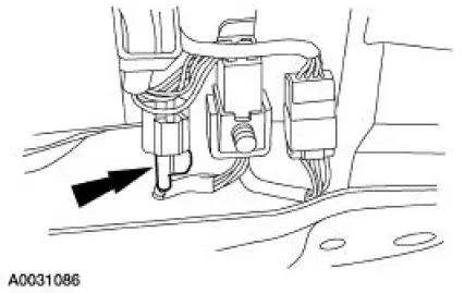
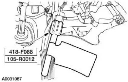
5. Attach the restraint system diagnostic tool to the vehicle harness side of the clockspring electrical connector.
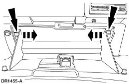
6. Open the glove compartment, push in on the tabs and open the glove compartment door to its fullest extent.
7. Remove the right hand A/C register duct.
- Remove the two screws retaining the duct to the A/C register.
- Separate the A/C duct at the air plenum and remove the duct.
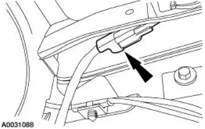
8. Disconnect the passenger air bag module.
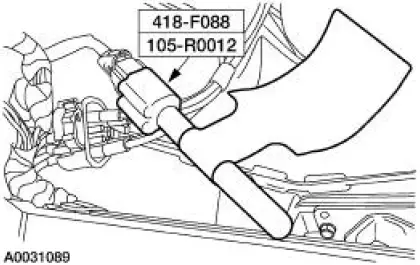
9. Attach the restraint system diagnostic tool to the vehicle harness side of the passenger air bag electrical connector.
10. Connect the battery ground cable. For additional information, refer to Section.
11. With the restraint system diagnostic tools installed at all deployable devices, prove out the supplemental restraint system (SRS). For additional information, refer to Air Bag Supplemental Restraint System (SRS) in the Diagnosis and Testing portion of this section.
12. Disconnect the battery ground cable and wait at least one minute. For additional information, refer to Section.
 Supplemental Restraint System (SRS) Deactivation and
Reactivation
Supplemental Restraint System (SRS) Deactivation and
Reactivation
Special Tool(s)
Diagnostic Tool, Restraint
System (2 Req'd)
418-F088 (105-R0012)
...
Other materials:
Diagnostic Instructions - Air Bag Supplemental Restraint
System (SRS)
Special Tool(s)
Worldwide Diagnostic System
(WDS)
418-F224,
New Generation STAR (NGS)
Tester
418-F052, or equivalent scan
tool
The symptom chart can be used to help locate the air bag supplemental
restraint system (SRS)
concerns if n ...
Installation
LH mount
1. Position the engine mount and install the bolt and studbolts.
2. Attach the ground cables and install the nuts.
RH mount
3. Position the engine mount and install the bolts and studbolt.
4. Attach the wiring harness and install the nut.
Both ...
Camshaft Runout
Special Tool(s)
Dial Indicator Gauge with
Holding Fixture
100-002 (TOOL-4201-C) or
equivalent
1. NOTE: Camshaft journals must be within specifications before
checking runout.
Use a Dial Indicator Gauge with Holding Fixture to measure the ...
