Ford Mustang (1999-2004) Service Manual: Removal
1. Remove the upper intake manifold. For additional information, refer to Upper Intake Manifold in this section.
2. Partially drain the cooling system. For additional information, refer to Section.
3. Relieve the fuel system pressure. For additional information, refer to Section.
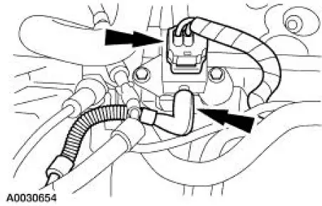
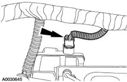
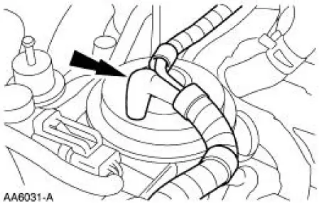
4. Disconnect the fuel rail pressure (FRP) sensor electrical connector and vacuum hose.
5. Disconnect the fuel supply tube spring lock coupling. For additional information, refer to Section.
6. Disconnect and position the engine wire harness aside.
7. Disconnect the intake manifold runner control (IMRC) electrical connector.
8. Remove the heater bypass tube. For additional information, refer to Section.
9. Disconnect the heater hose.
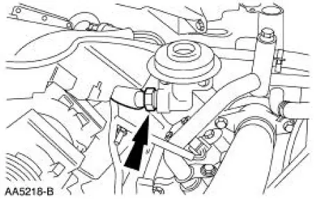
10. Disconnect the exhaust gas recirculation (EGR) vacuum tube.
11. Disconnect the EGR tube from the EGR valve.
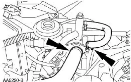
12. Disconnect the radiator upper hose and coolant bypass hose.
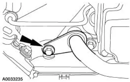
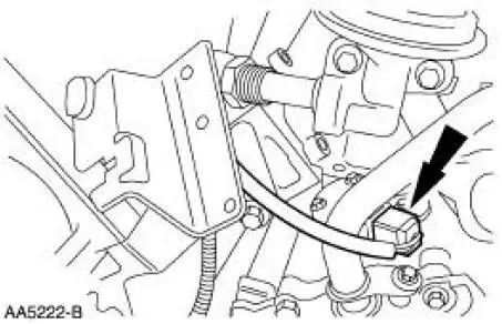
13. Disconnect the electrical connector.
14. NOTE: Remove the fuel injection supply manifold and fuel injectors as an assembly.
Remove the bolts and the fuel injection supply manifold.
15. NOTE: For ease in installation, record the location of the short bolts and the long bolts.
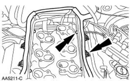
Remove the lower intake manifold.
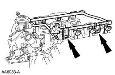
1. Remove the eight short bolts.
2. Remove the six long bolts.
3. Remove the lower intake manifold.
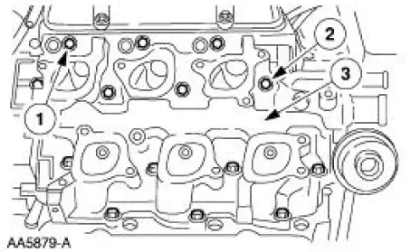
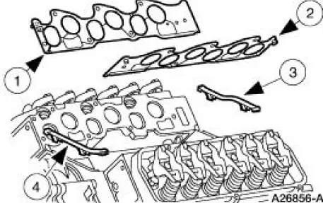
16. Remove and discard the intake manifold gaskets.
 Lower Intake Manifold
Material
...
 Installation
1. NOTE: If the lower intake manifold is not secured within four
minutes, the sealant must be
removed and the sealing area cleaned with metal surface cleaner. Allow to
dry until there is no
sign ...
Other materials:
Interior Lighting (Diagnosis and Testing)
Refer to Wiring Diagrams Cell 111 , Remote Control Alarm and Lock System
for schematic and
connector information.
Refer to Wiring Diagrams Cell 59 , Generic Electronic Module for schematic
and connector
information.
Refer to Wiring Diagrams Cell 89 , ...
Pinpoint Test O: DTC B1870 - Air Bag Indicator Shorted to Battery
Normal Operation
The air bag indicator is designed to illuminate for 6 (+/-2) seconds
when the ignition switch is turned to
the RUN position. This initial 6 seconds of illumination is considered
normal operation and is called
proveout of the air ba ...
Tracer Dye Leak Detection
Special Tool(s)
120 Watt 110 Volt UV Lamp
20C
164-R0721 or equivalent
NOTE: Ford Motor Company vehicles are produced with a permanent leak
tracer dye incorporated into
the A/C system. The location of leaks can be pinpointed by the bright
ye ...
