Ford Mustang (1999-2004) Service Manual: Valve Springs
Special Tool(s)
|
|
Compressor, Valve Spring 303-163 (T81P-6513-A) |
Material
Removal
1. Remove the LH and the RH valve covers. For additional information, refer to Valve Cover-LH and Valve Cover RH in this section.
2. Rotate the crankshaft until the piston for the valve being worked on is at the top of its stroke with both the intake valve and the exhaust valve closed.
3. Hold the valve in the cylinder head.
- Remove the spark plug. For additional information, refer to Section.
- Apply a minimum of 965 kPa (140 psi) of compressed air into the cylinder.
4. CAUTION: If the components are to be reinstalled, they must be installed in the same position. Mark the components for location.
NOTE: If a valve drops into the cylinder, remove the cylinder head. For additional information, refer to Cylinder Head LH or Cylinder Head RH in this section.
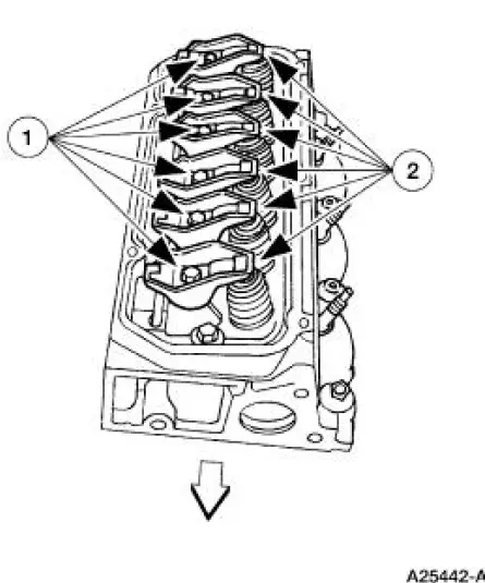
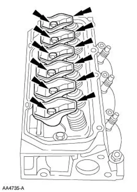
Remove the rocker arms.
1. Remove the bolts.
2. Remove the rocker arms.
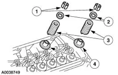
5. Using the special tool, compress the valve springs.
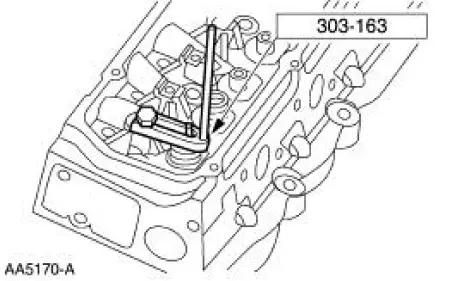
6. Remove the valve spring assembly.
1. Remove the valve spring retainer key.
2. Remove the valve spring retainer.
3. Remove the valve spring.
4. Remove and discard the valve stem seal and spring seat assembly.
7. Inspect the components. For additional information, refer to Section.
Installation
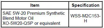
1. NOTE: Lubricate the parts with clean engine oil.
To install, reverse the removal procedure. Tighten the rocker arm bolts in two stages.
- Stage 1: Tighten to 5 Nm (44 lb-in).
- Stage 2: Tighten to 35 Nm (26 lb-ft).
 Push Rod
Removal
CAUTION: Mark the components removed for correct location.
1. Remove the rocker arms (6564). For additional information, refer to
Rocker Arm in this section.
2. Remove the push rods (656 ...
 Valve Tappets
Material
Removal
CAUTION: If removing more than one valve tappet, mark the
components removed for
correct location.
1. Remove the lower intake manifold. For additional information, refer to
Lo ...
Other materials:
Valve Spring Strength
Special Tool(s)
Pressure Gauge, Valve/Clutch
Spring
303-006 (TOOL-6513-DD) or
equivalent
1. Use a Valve/Clutch Spring Pressure Gauge to check the valve spring for
correct strength at the
specified valve spring length.
Refer to the appr ...
Master Cylinder - Hydro-Boost
Removal
1. Disconnect the fluid level sensor connector.
2. Disconnect the brake tubes.
3. Remove the brake master cylinder nuts.
4. Remove the brake master cylinder (2140).
Installation
1. To install, reverse the removal procedure.
Bleed the brak ...
Inspection and Verification
1. The keyless entry system is a generic electronic module (GEM).
2. Verify the customer concern by using the remote transmitters to
operate the keyless entry
system.
3. Visually inspect for the following obvious signs of mechanical and
electrica ...
